

Introduction
The purpose of this guide
The primary objective of vMeasure Parcel Ultima Gold is to save user’s time and reduce the efforts taken for dimensioning SKU at a warehouse. That being the case, the user shouldn’t be wasting time with the product setup. Therefore, this installation manual seeks to simplify the process with images and vivid descriptions of each step in detail.
This manual will reduce the operator’s dependency on the customer support team of VisAI Labs. It ensures a seamless acquaintance with vMeasure Parcel Ultima Gold.
How to use this guide?
This document will provide detailed information on how to install, calibrate, and use vMeasure Parcel Ultima. The manual gives step-by-step instructions for all the key steps in clear and easy-to-understand language. If you have any more queries, reach out to vmeasure@visailabs.com.
To enhance the ease of following commands, images and video links to that specified task have been provided at every step of the process.
Perform each task as instructed in the manual to avoid any discrepancies or errors in the product.
Summary of the Installation Manual
Setting up the device consists of the following three segments:
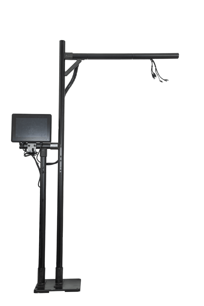
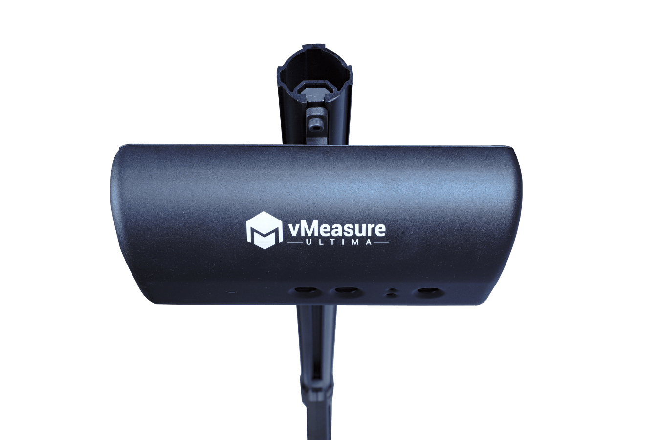
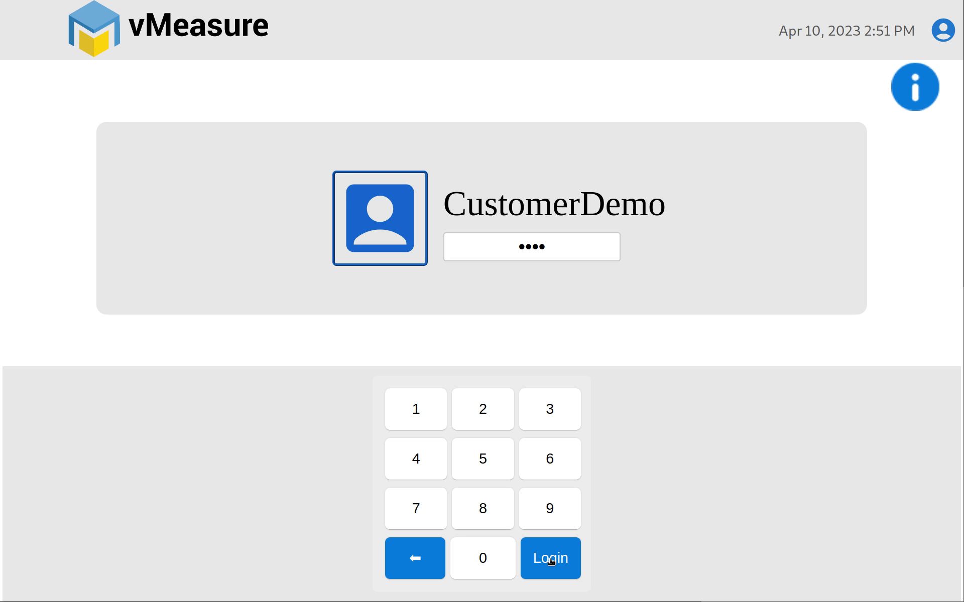
Figure 1: Major Installation Steps
Each of these segments require multiple low-effort steps to complete. It is as simple as tightening a few screws in place, sliding clamps onto the pole, and connecting cables at appropriate places.
Introduction to the Product
vMeasure Parcel Ultima is a vision-based measurement system that can dimension SKUs. It comes with an in-built camera that captures photos of the measured objects. It can be connected to the Cloud using vMeasure Forge for data backup and analytics. The Vision Head Unit (VHU) in the vMeasure Ultima is classified as a CLASS 1 Laser Product under the EN/IEC 60825-1:2014 (EU).
The Vision Head Unit is also called VHU or Vision box.
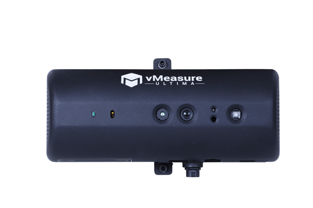
Figure 2: Vision Head Unit – Bottom View
The bottom view of VHU consists of three cameras, IR sensor, and LED light as shown below.
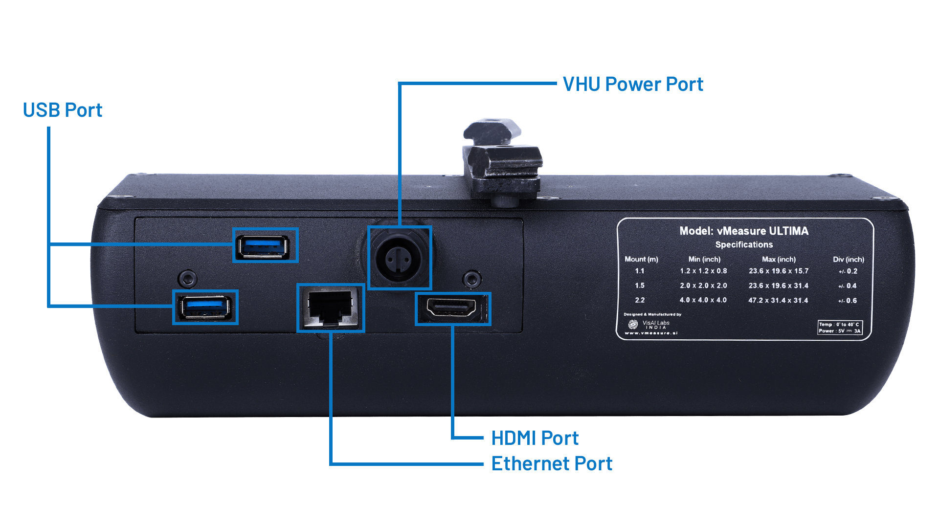
Figure 3: Vision Head Unit – Back View
The back view of VHU consists of two USB ports,one HDMI port, an ethernet port, and VHU Power port.
Unbox and Components
Contents of the package

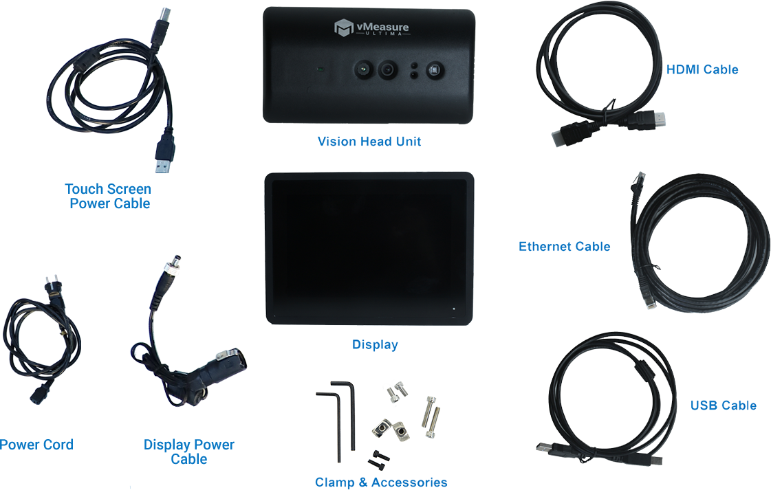
Figure 6: Parts required for setup
| S.No | Items | Quantity |
|---|---|---|
| 1 | Profile Clamp | 1 |
| 2 | Allen Key 3mm | 1 |
| 3 | Allen Key 4mm | 1 |
| 4 | M5 x 25 Allen bolt MS blackened finished | 2 |
| 5 | M5 x 10 Allen bolt MS blackened finished | 2 |
| 6 | M5 T nut MS plating finished | 2 |
| 7 | M4 x 8 Allen MS blackened | 2 |
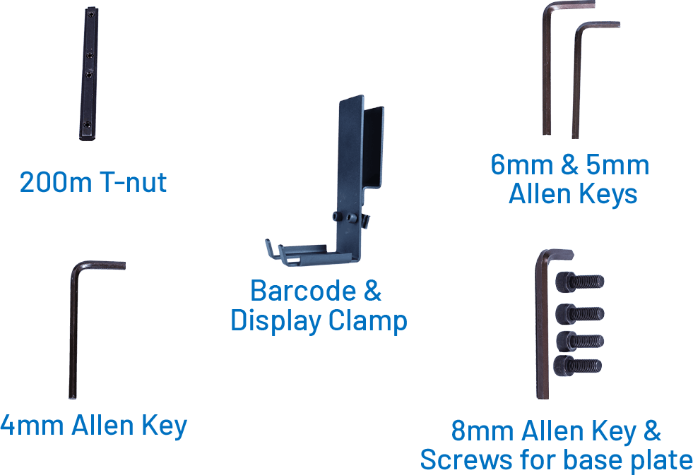
Fig. 7 – Clamp and Accessories
Installation Guide
Setting up the pole
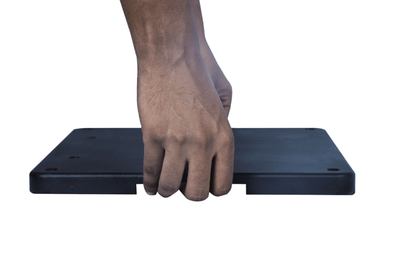
Fig. 8 – Base Plate Placement
Step 1: Place the baseplate on a flat and steady surface.
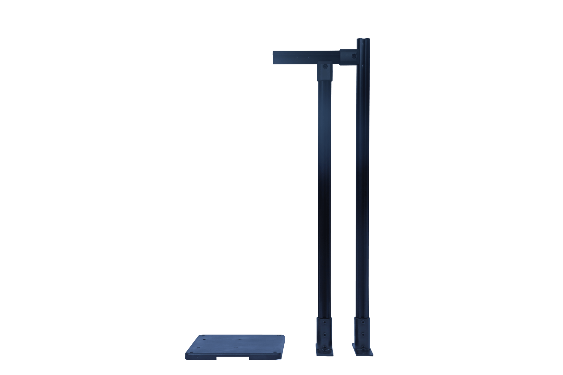
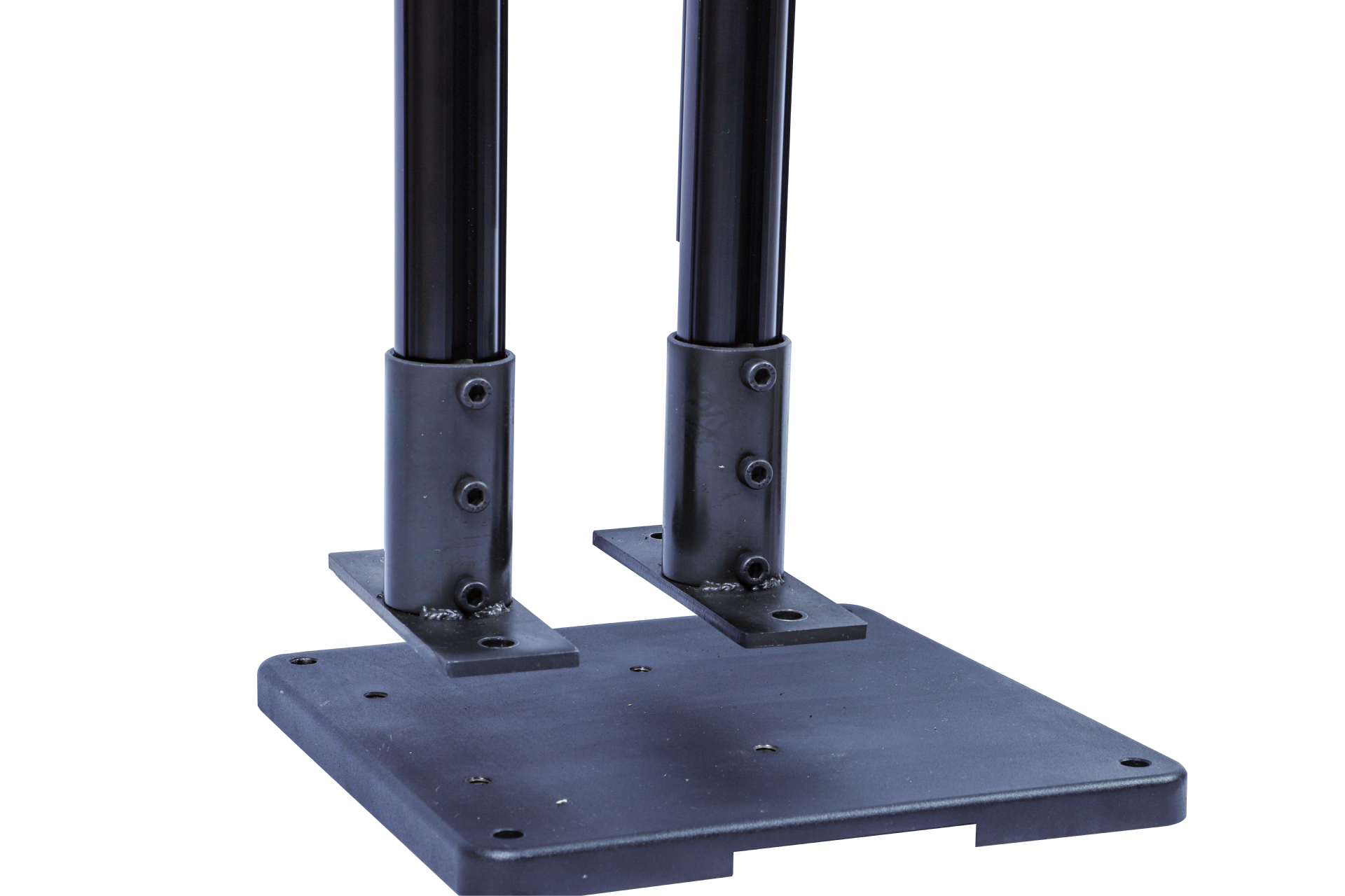
Fig. 9 – Pole Placement on the Base Plate
Step 2: Take the base pole with the coupler and fix it on the baseplate according to the markings provided in the image.
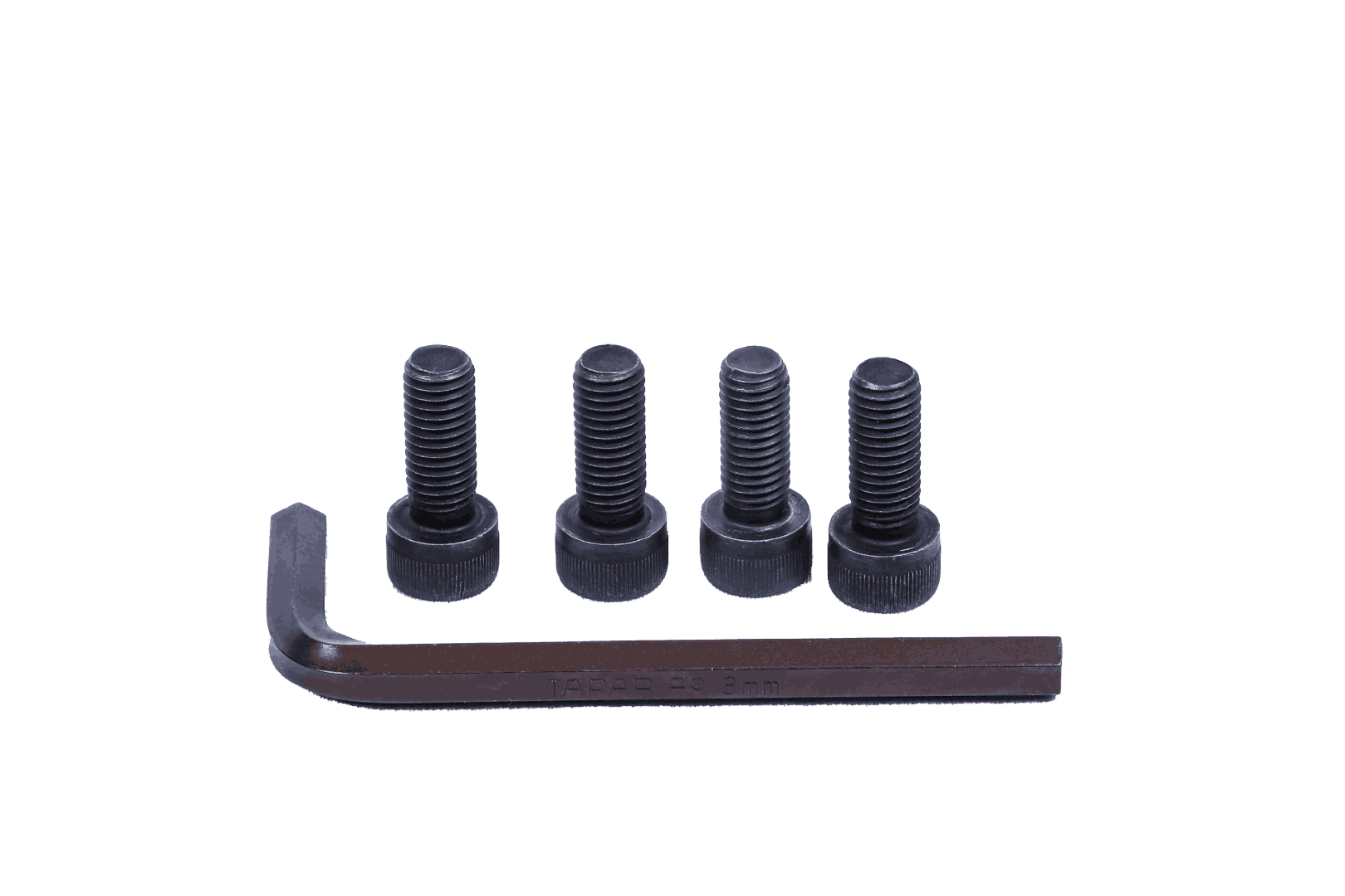
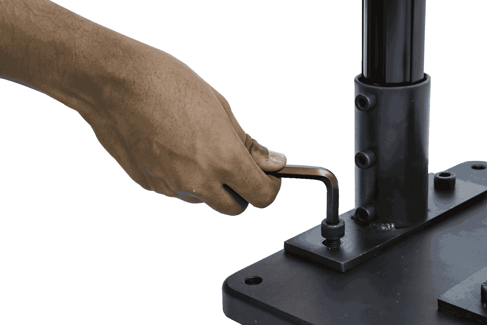
Fig. 10 – Allen Keys and Bolts; Fixing the Pole
Step 3: Screw the M10 x 25 mm bolt using the 8 mm Allen Key.
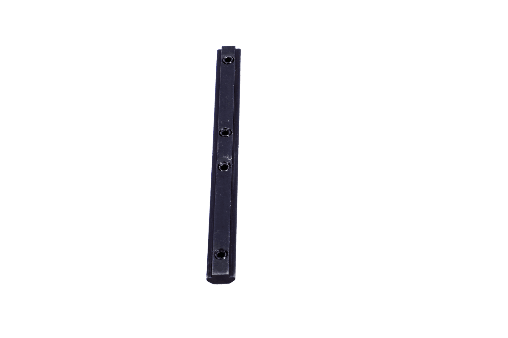
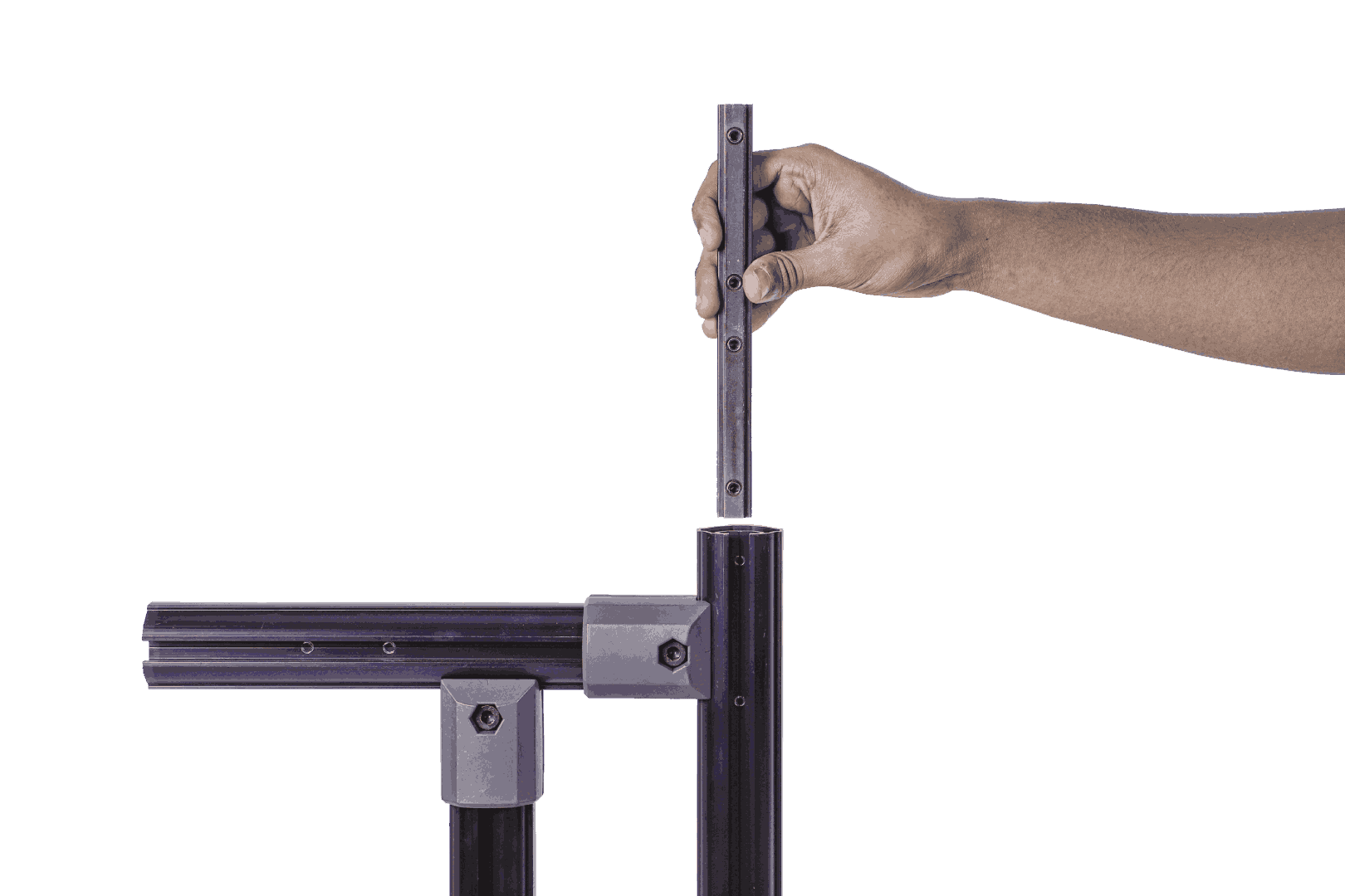
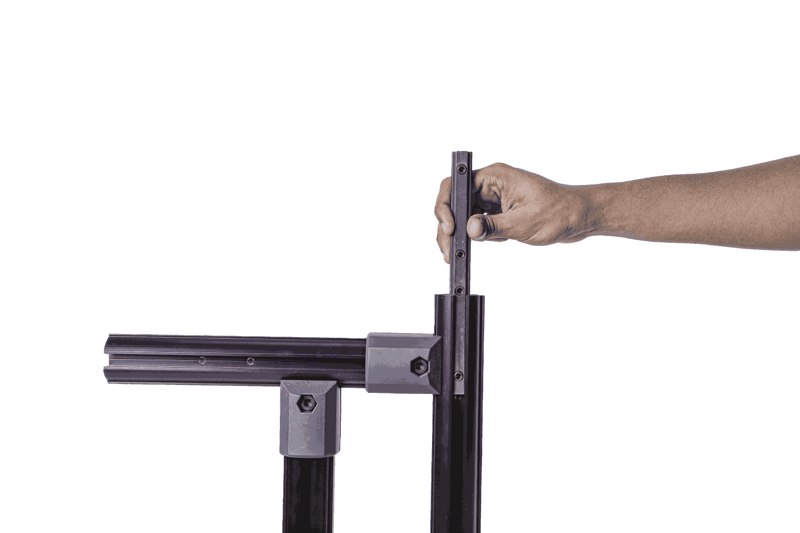
Fig. 11 – Long T-Nut Placement
Step 4: Insert the Long T-nut in the slot as shown in the image.
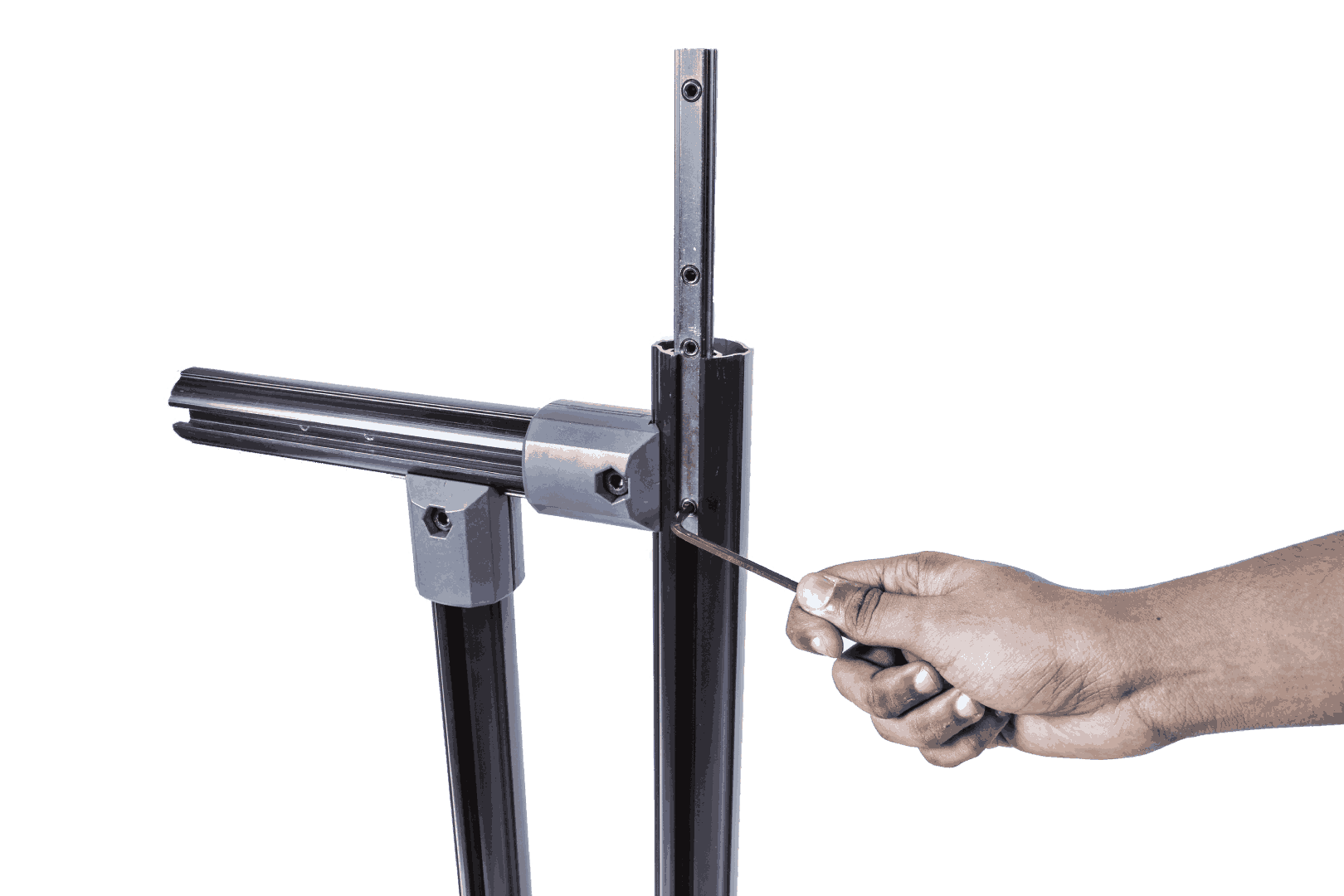
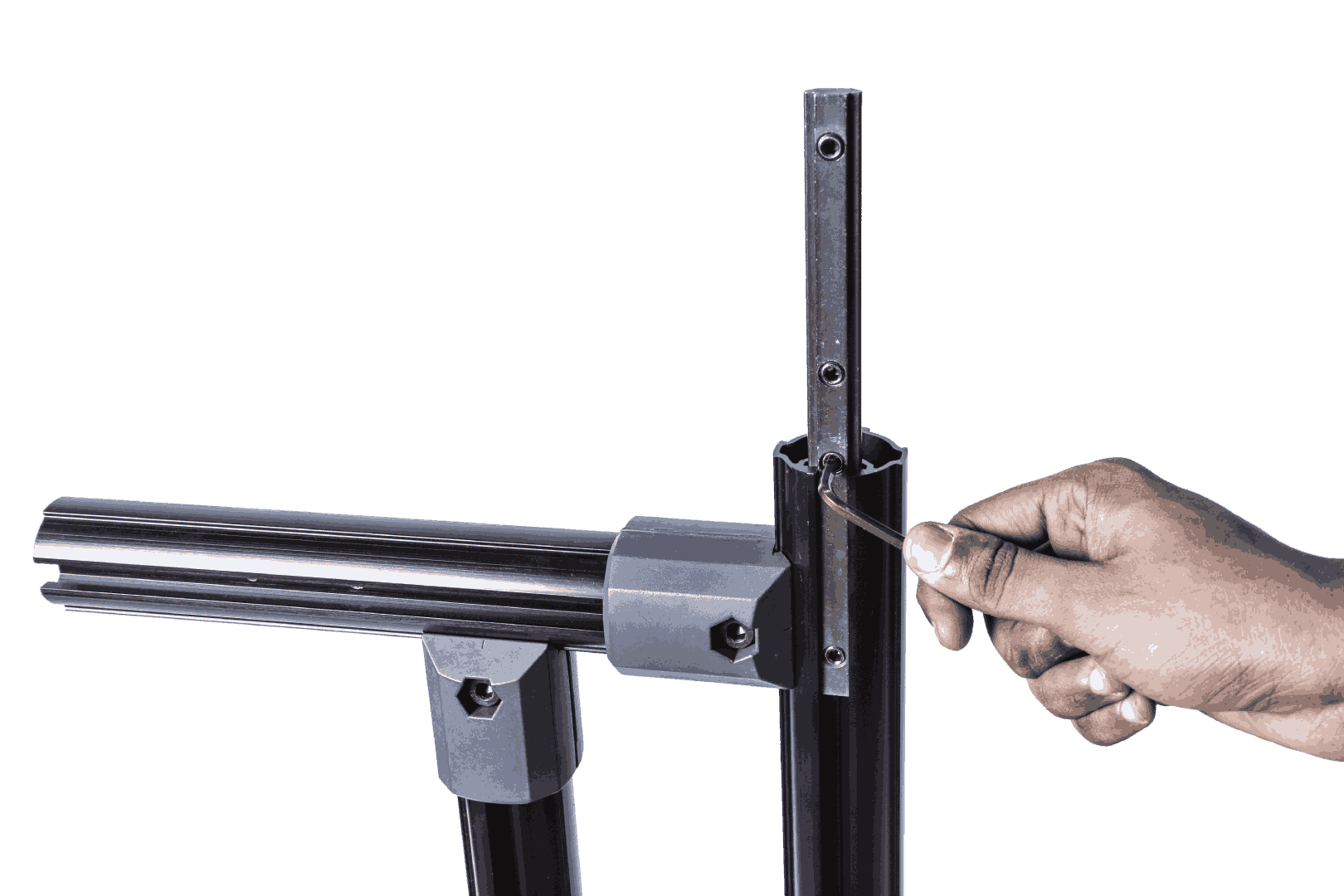
Fig. 12 – Fixing the Long T-Nut
Step 5: Tighten the two grub screws on the Long T-nut with the 4 mm Allen key.
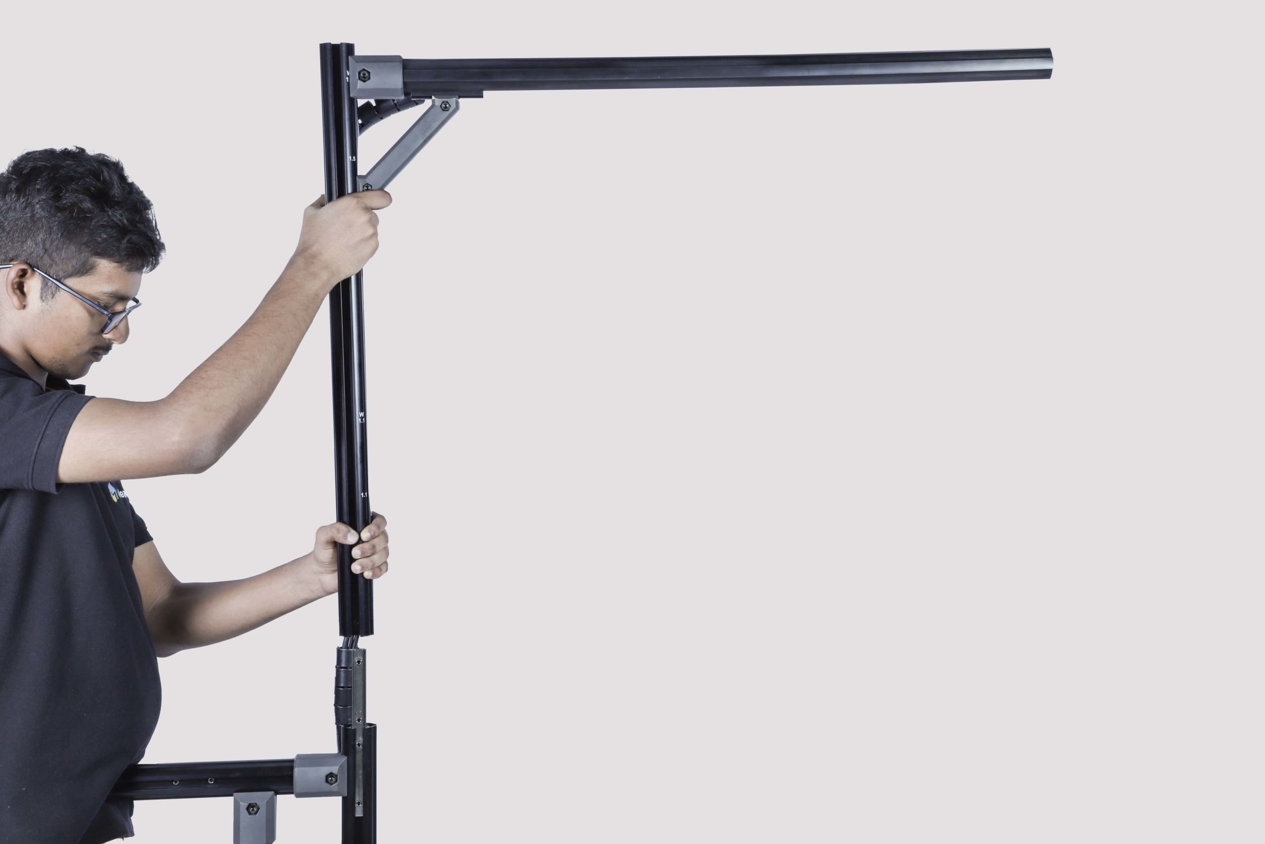
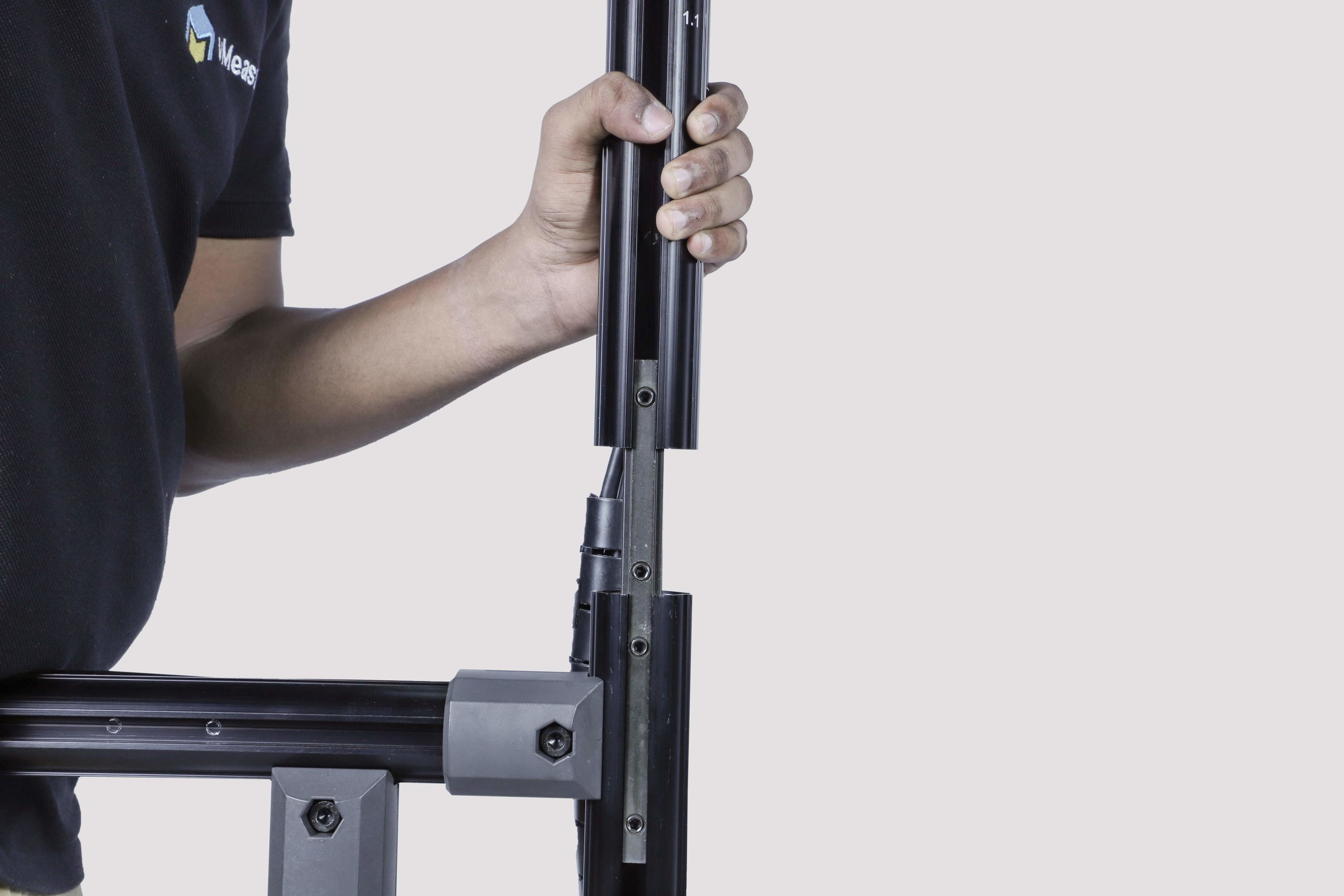
Fig. 13 – Fixing the Top Pole
Step 6: Slide the top pole with arm into the Long T-nut
Installation and connection of the accessories
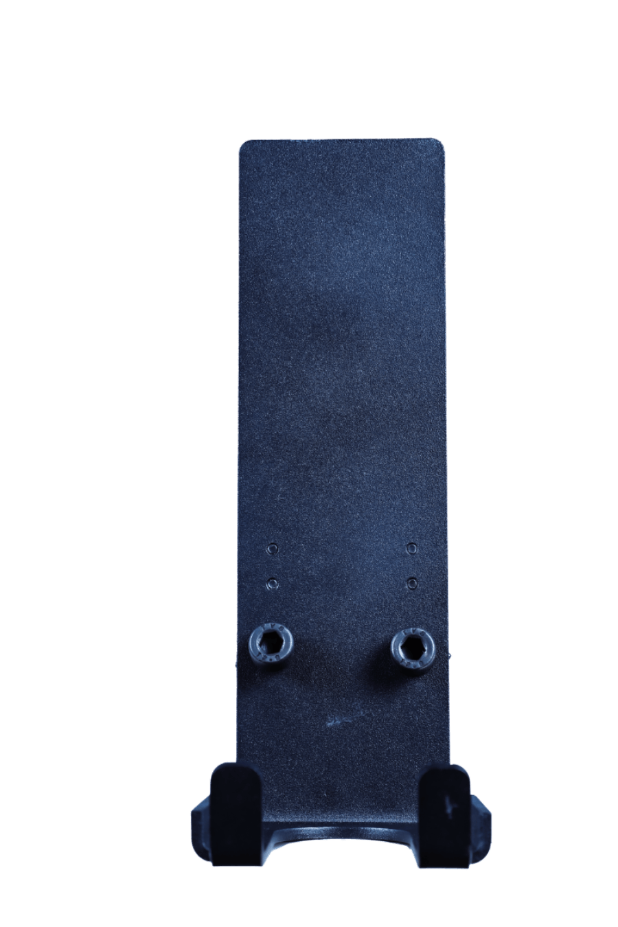
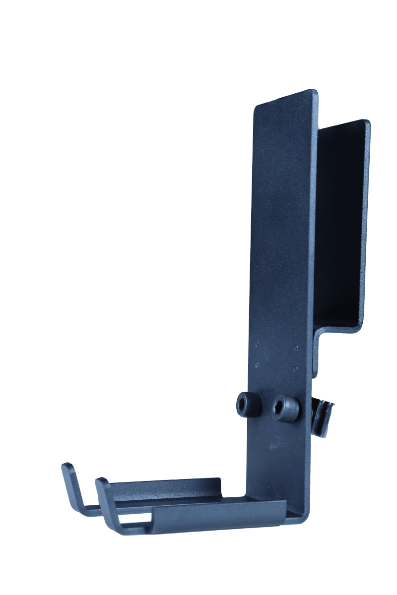
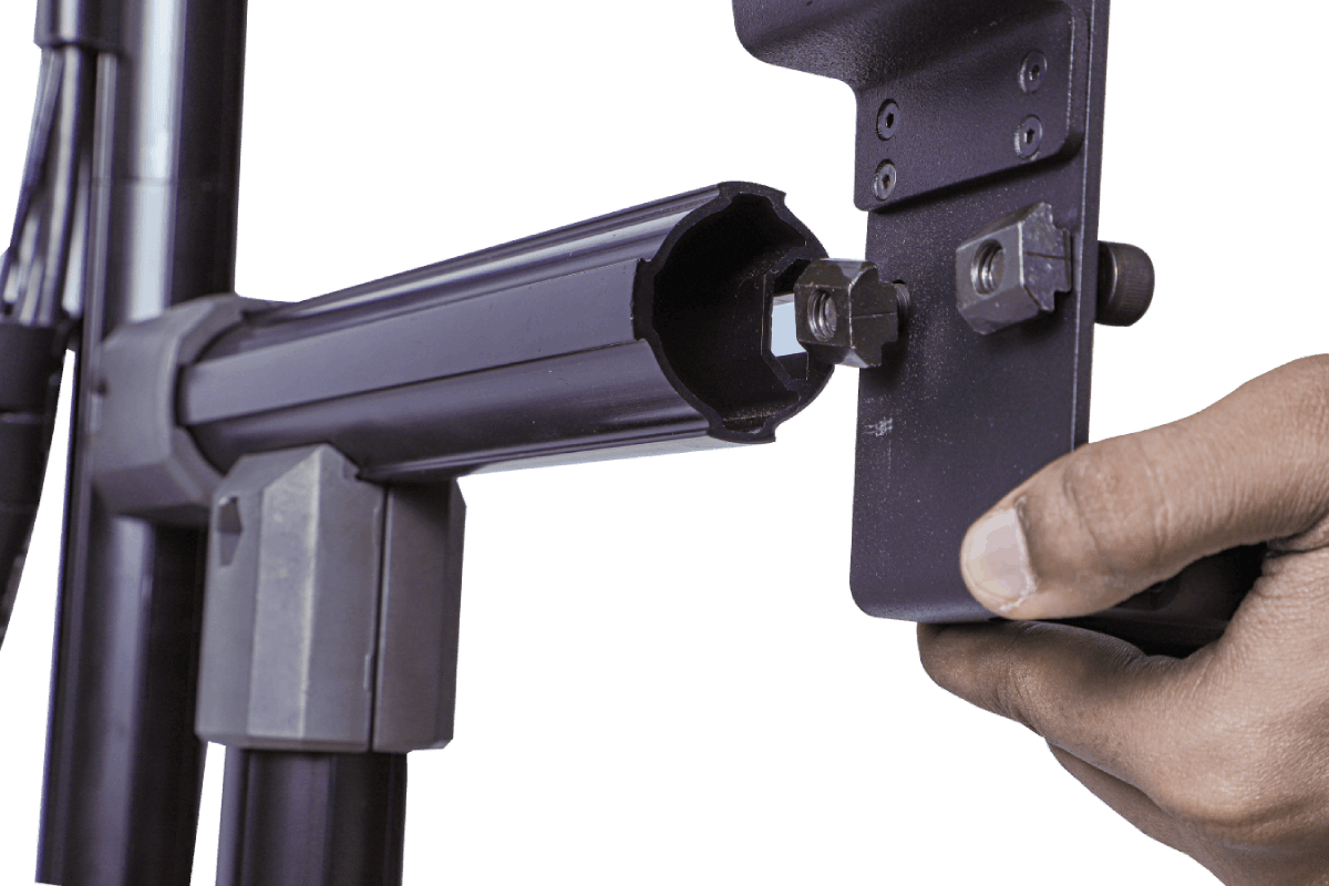
Fig. 14 – Accessory Clamp Installation
Step 1a: Slide the accessory clamp to the pole.
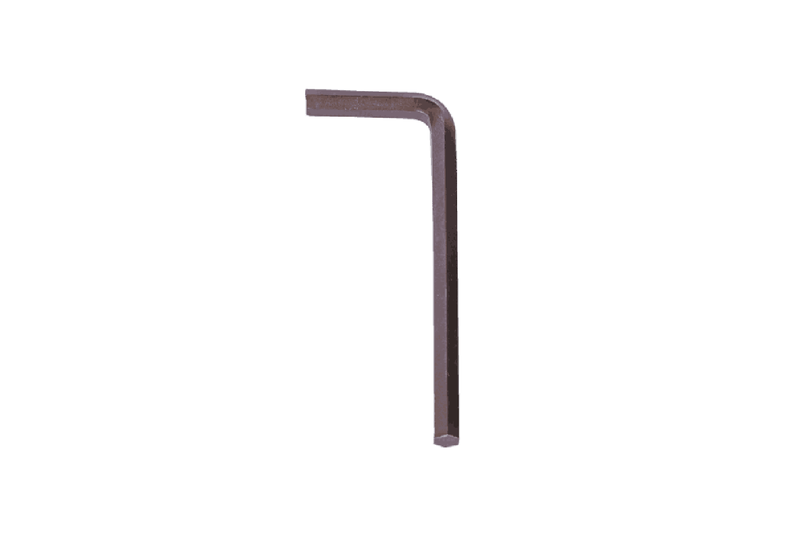
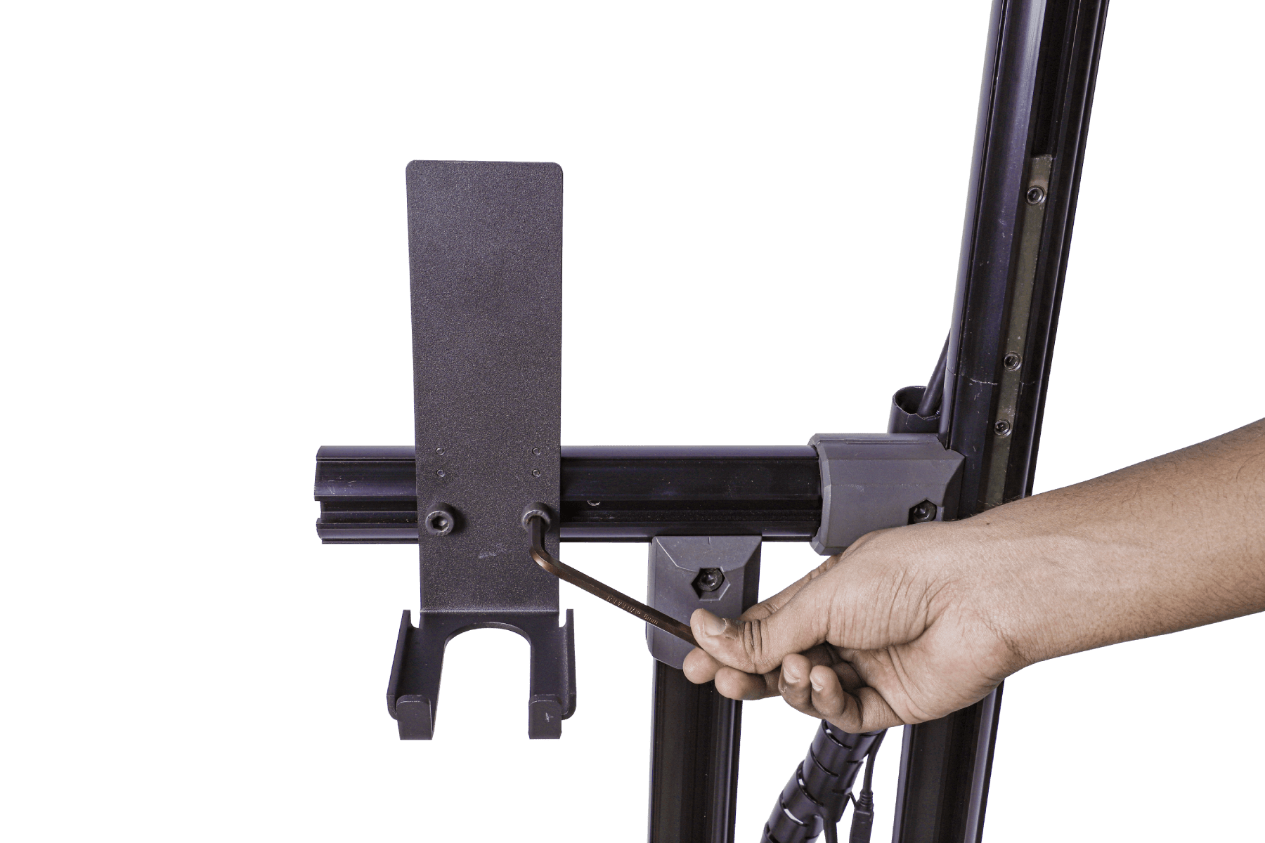
Fig. 15 – Fixing the Accessory Clamp
Step 1b: Tighten the clamp using a 6 mm Allen Key.
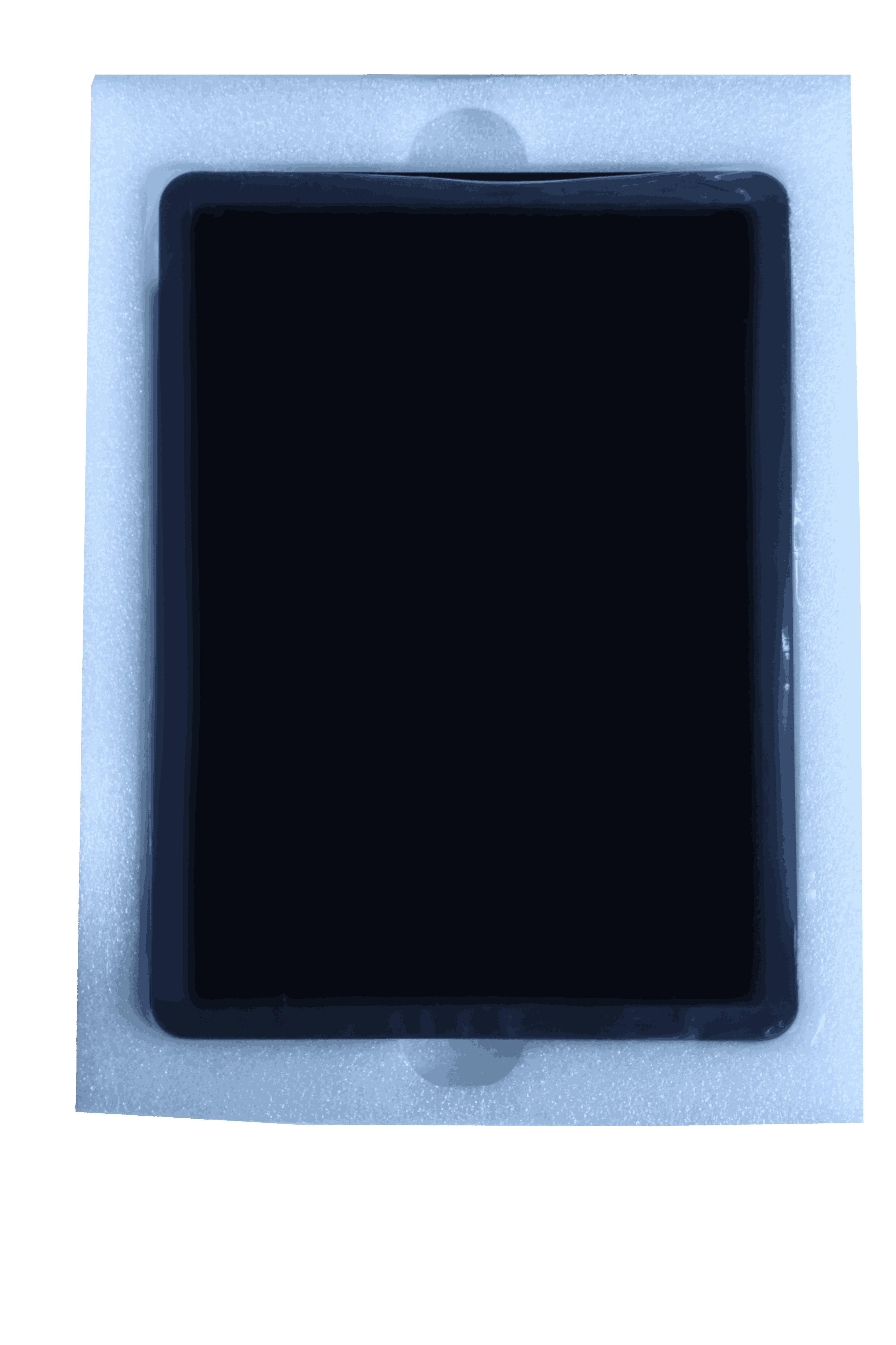
Fig. 16 – Touchscreen Display
Step 2: Take out the display unit.
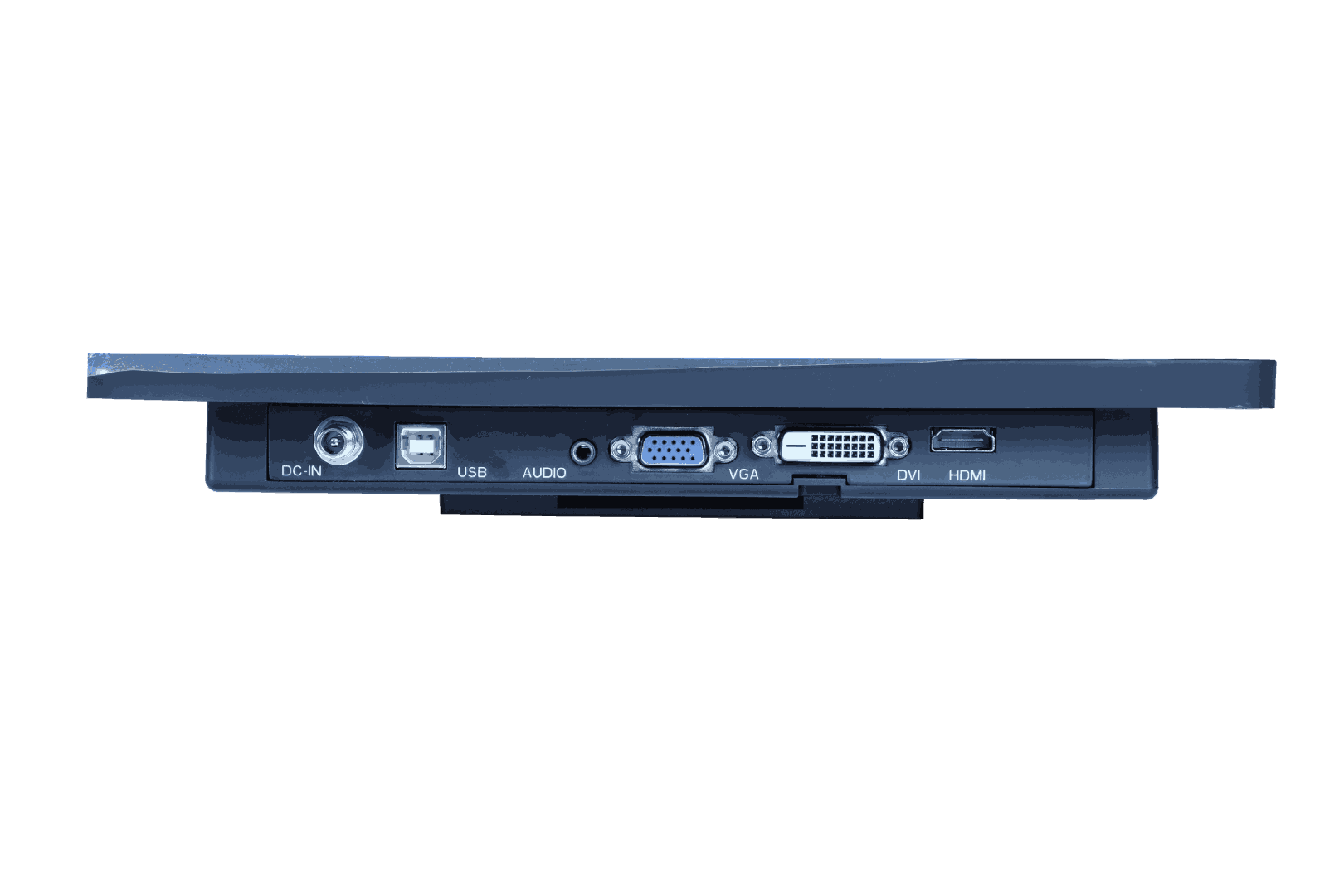
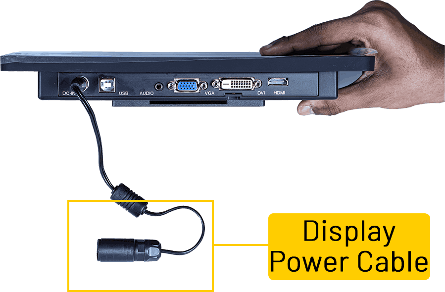
Fig. 17 – Fixing the Display Power Cable
Step 2a: Connect the power cable to the marked area on the display unit.
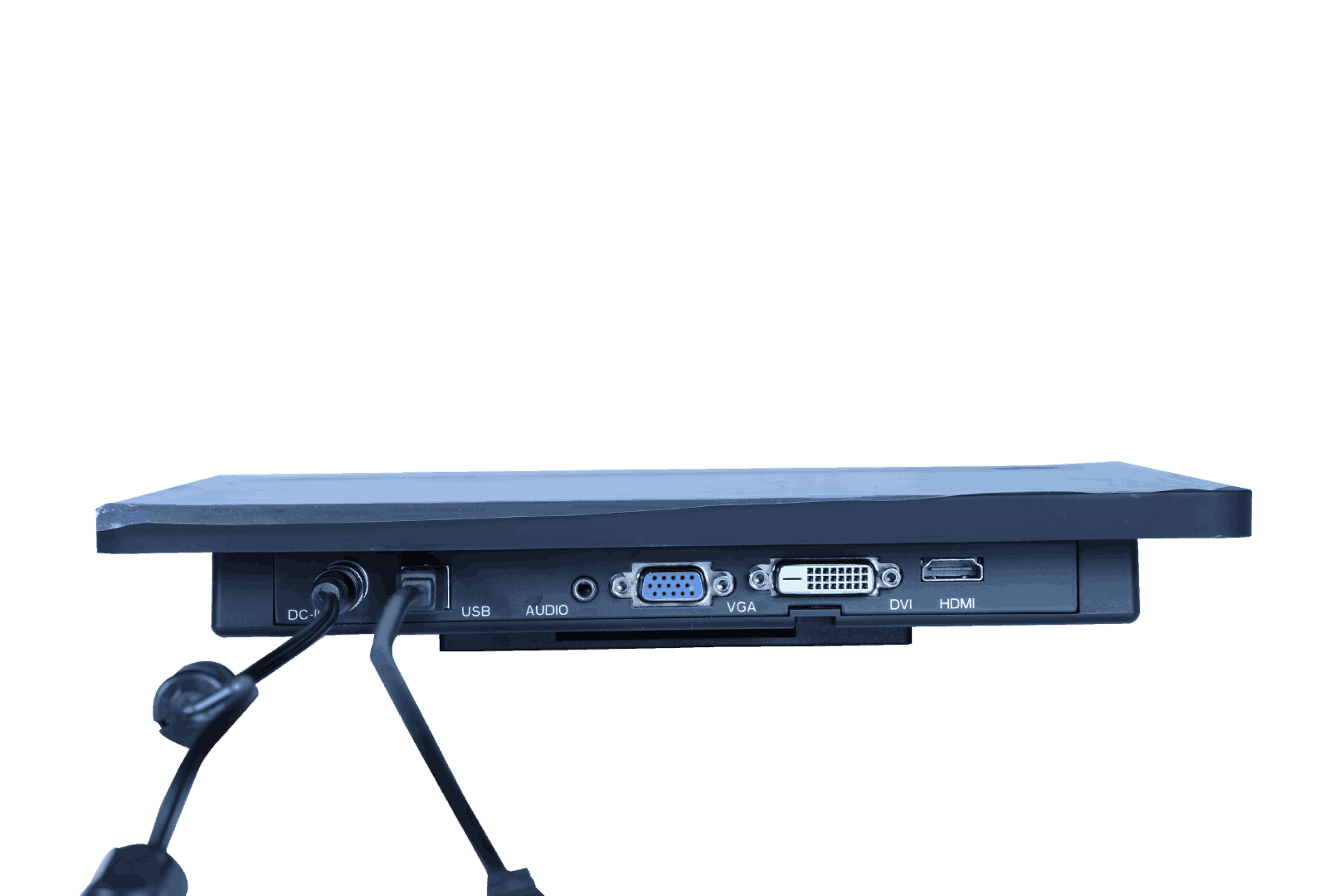
Fig. 18 – Fixing the Touch Input Cable
Step 2b: Plug the USB cable to the designated port on the display unit and the other end to one of USB ports in the power box (discussed later in this section).
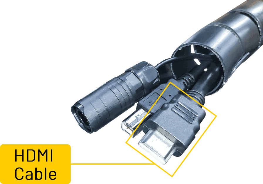
Fig. 19 – Fixing the HDMI Cable
Step 2c: Connect the HDMI cable from the VHU to the marked port on the display unit
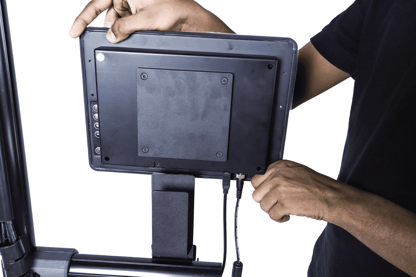
Fig. 20– Touchscreen Display Placement
Step 3: Slide the display unit on the clamp.
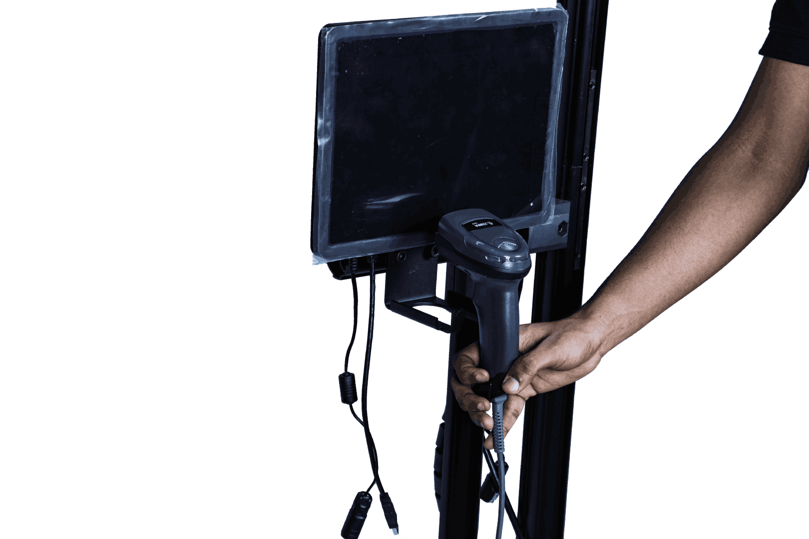
Fig. 21 – Barcode Placement
Step 4: Place the barcode scanner on the stand.
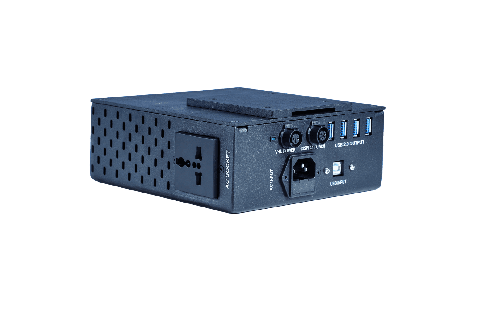
Fig. 22 – Power Box
Step 5a: Take the power unit.
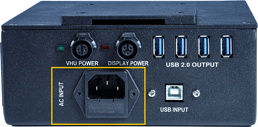
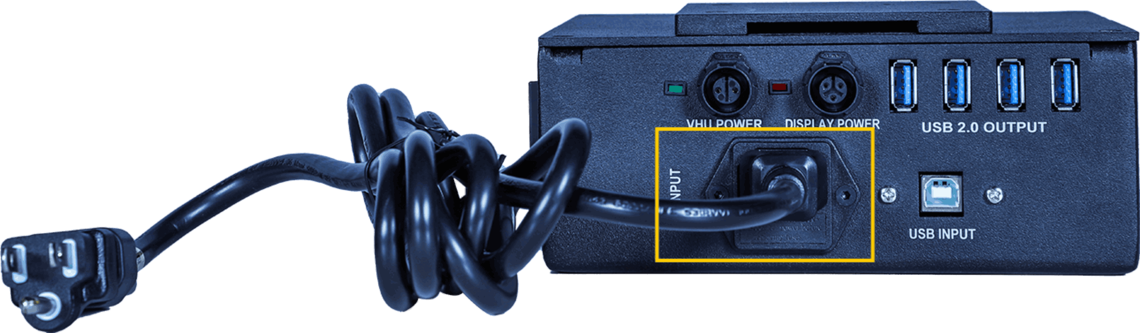
Fig. 23 – Fixing the AC Input Cable
Step 5b: Plug the AC input cable to the marked port on the power box. Connect the other end to a power source.
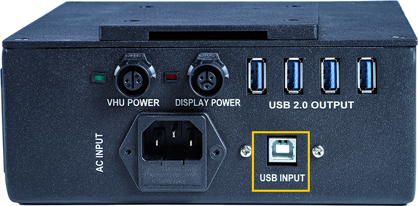
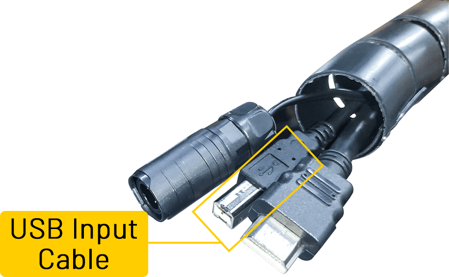
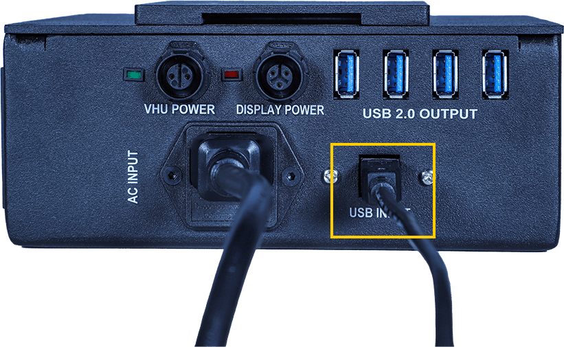
Fig. 25 – Fixing the USB Input Cable
Step 5c: Plug the USB cable from the VHU to the marked port on the power box.
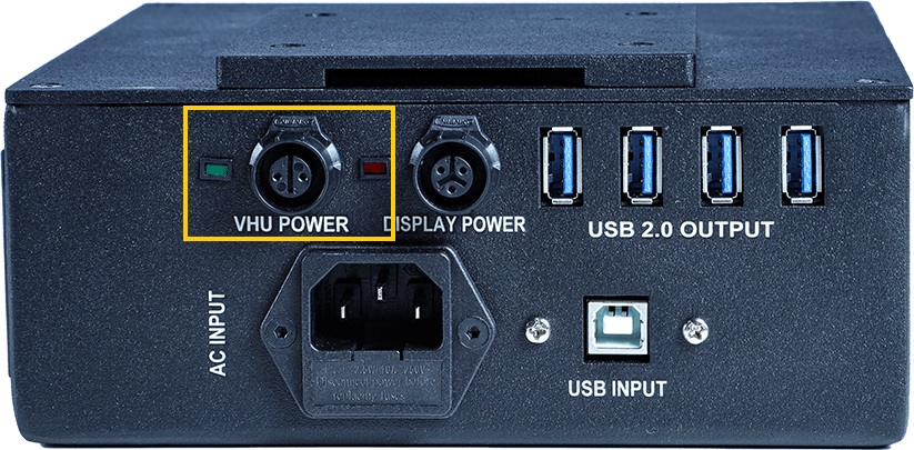
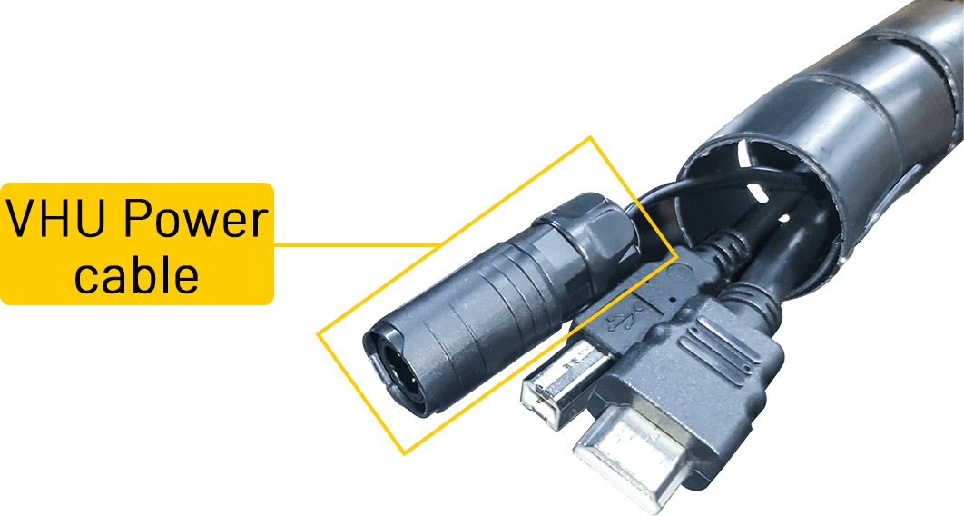
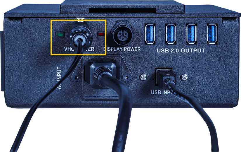
Fig. 26 – Fixing the VHU Power Cable
Step 5d: Connect the Vision Head Unit Power cable to the designated port on the power box.
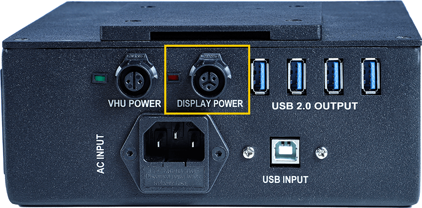
Fig. 27 – Fixing the Display Power Cable
Step 5e: Plug the display power to the marked area of the power box.
Refer to this segment of the video to get a better understanding of the above steps:
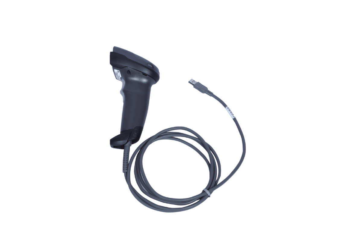
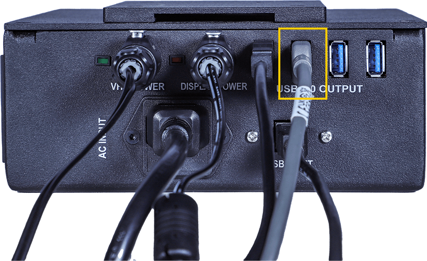
Fig. 28 – Fixing the Barcode Scanner Cable
Step 5f: Plug the Barcode scanner cable in one of the USB ports.
Connection of Weighing Scale
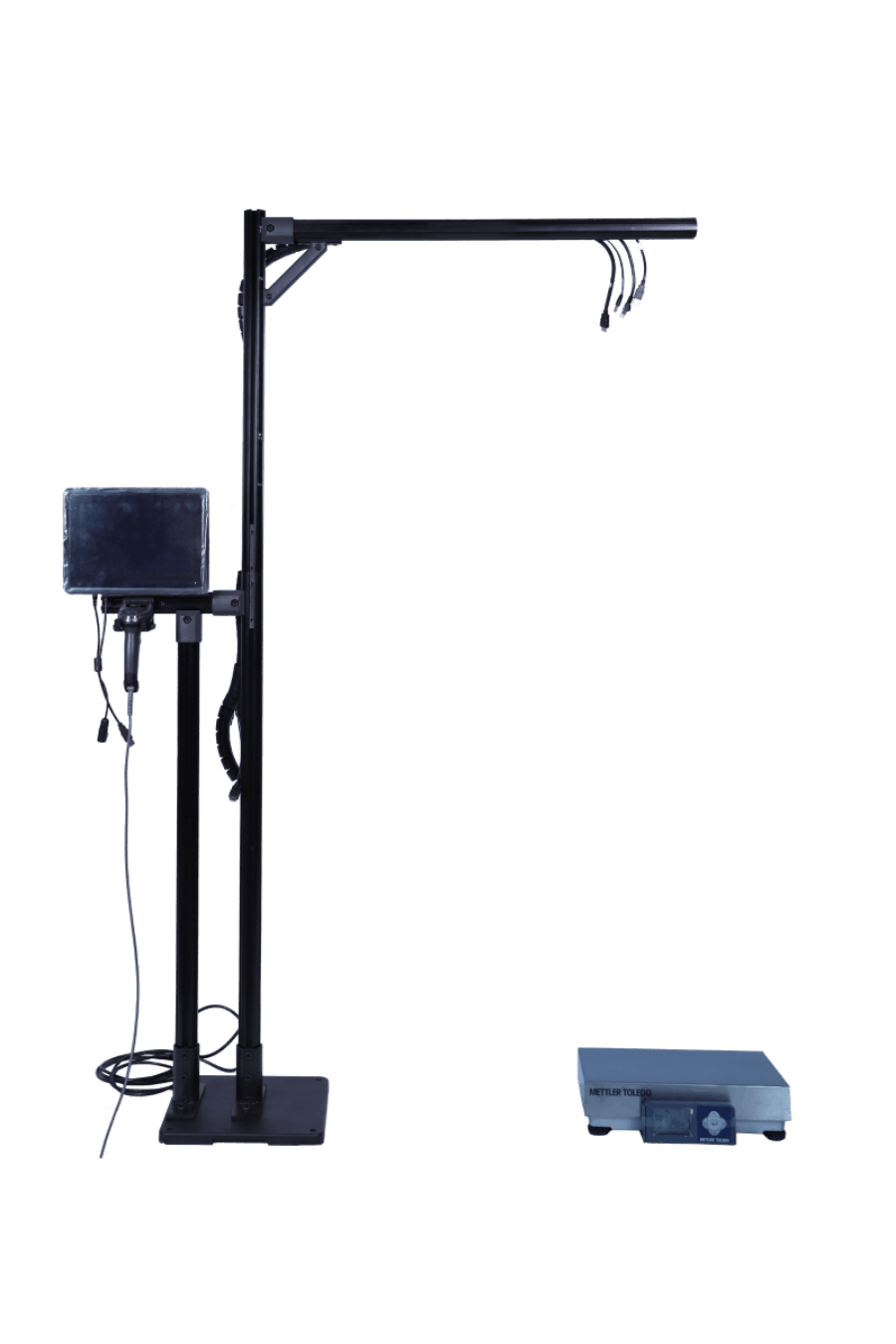
Fig. 29 – Weighing Scale Installation
Step 6a: Place the weighing scale under the Vision Head Unit.
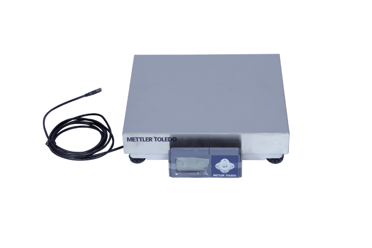
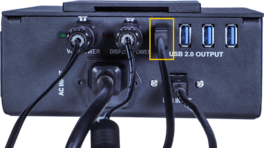
Fig. 30 – Fixing the Weighing Scale Cable
Step 6b: Plug the weighing scale cable to one of the USB ports.
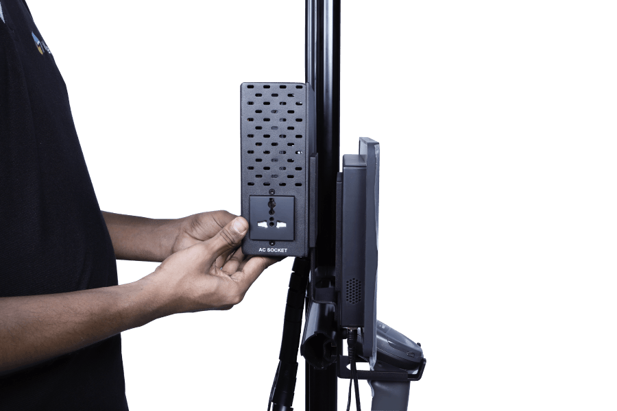
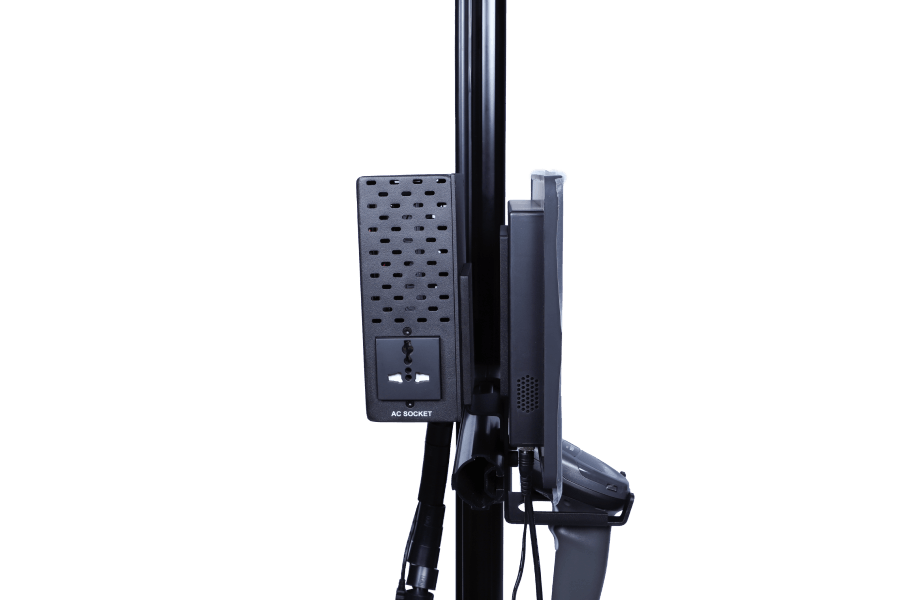
Fig. 31 – Power Box Installation
Step 7: Slide the Power box into the clamp behind the Display
Installation of the Vision Head Unit
Fixing Vision Head Unit to the pole

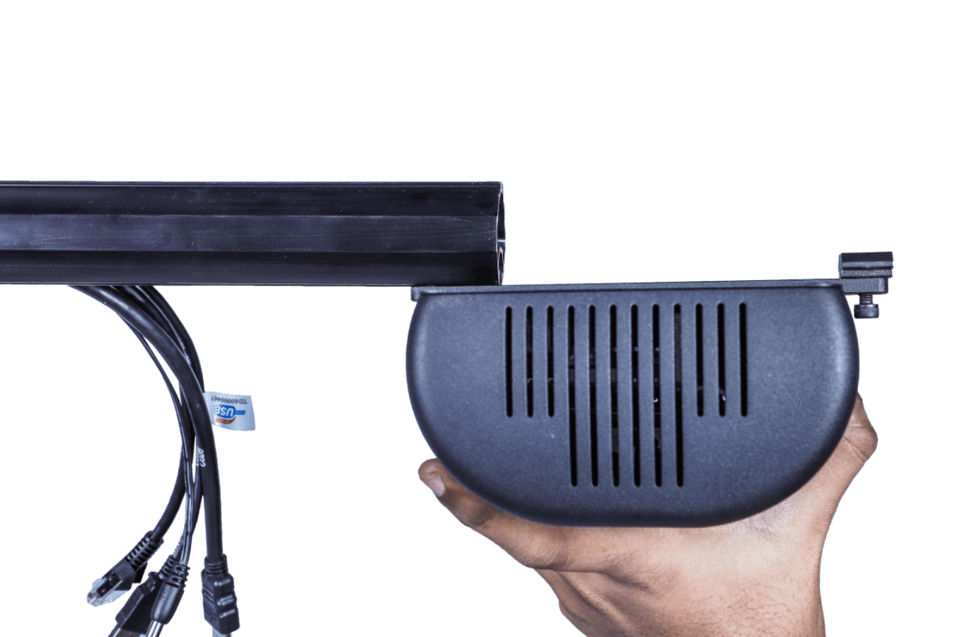
Fig. 32 – Vision Head Unit Installation
Step 1: Slide the VHU into the pole arm using the T-nut.
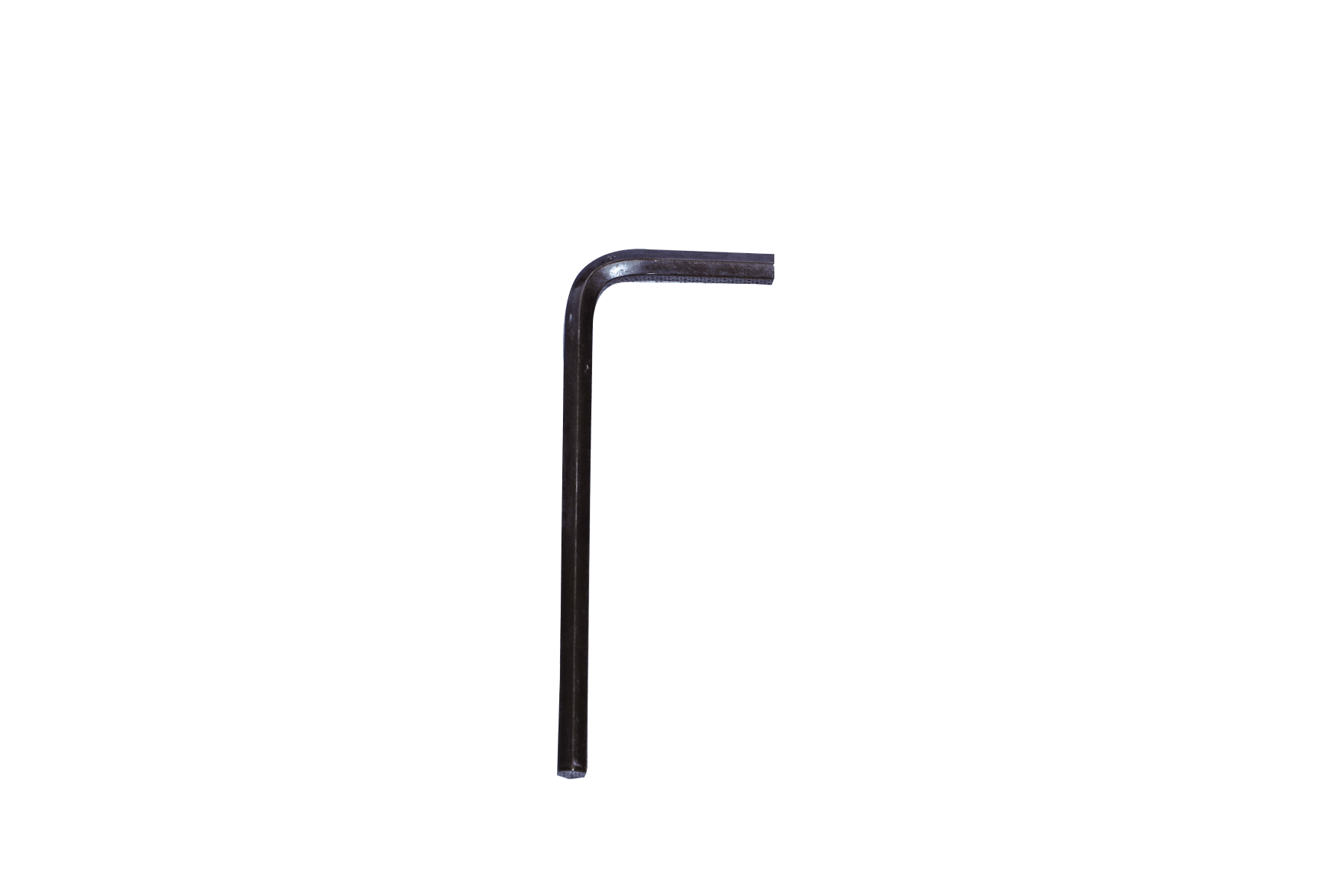
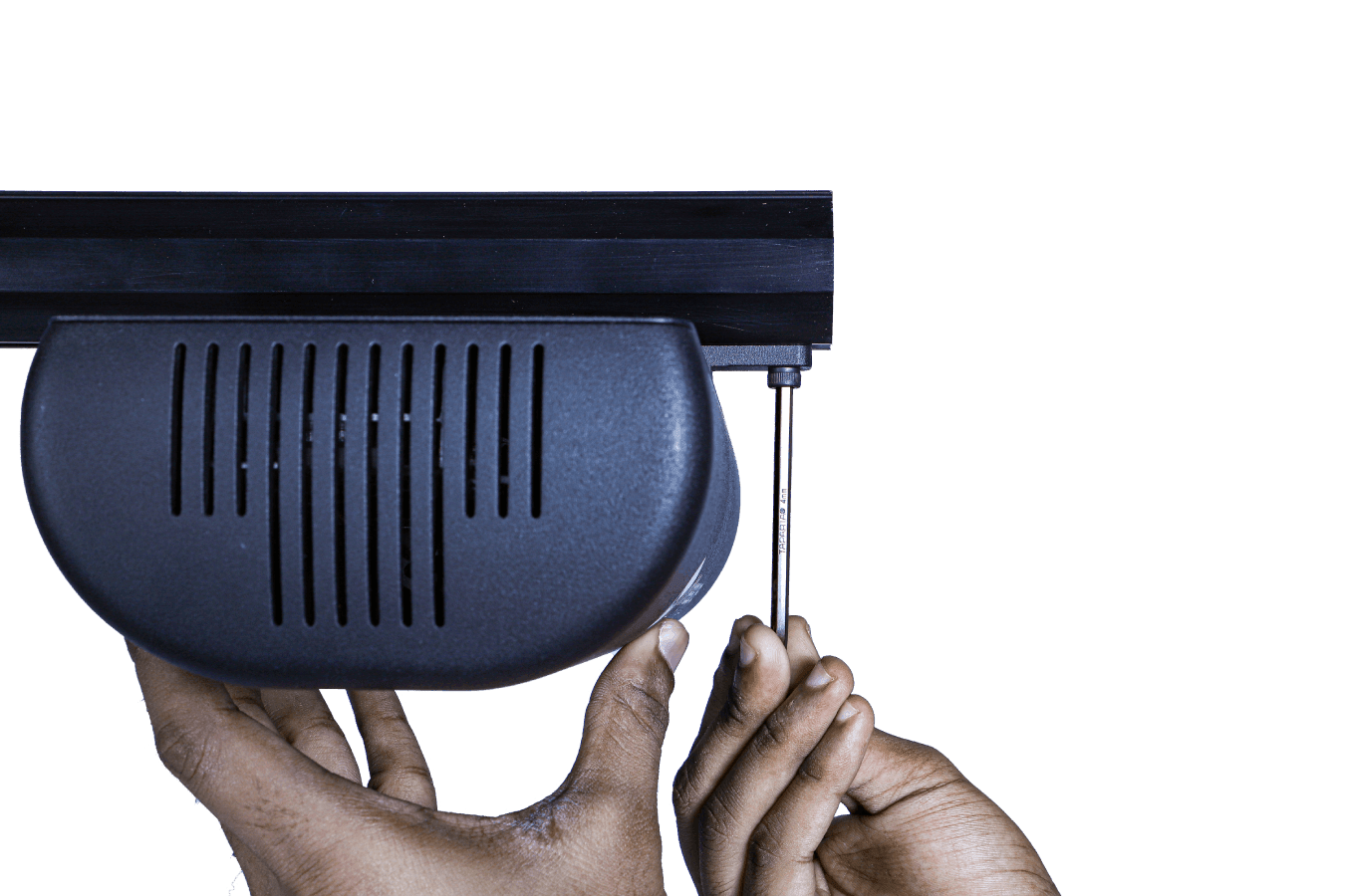
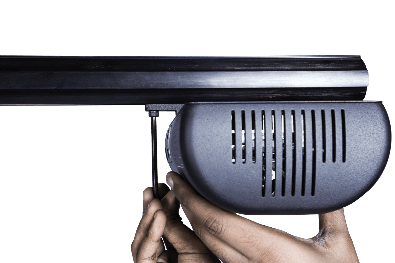
Fig. 33 – Fixing the Vision Head Unit
Step 2: Secure the VHU to the pole using the 4 mm Allen key.
Connections to the VHU
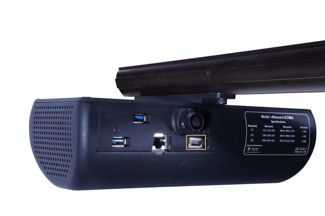
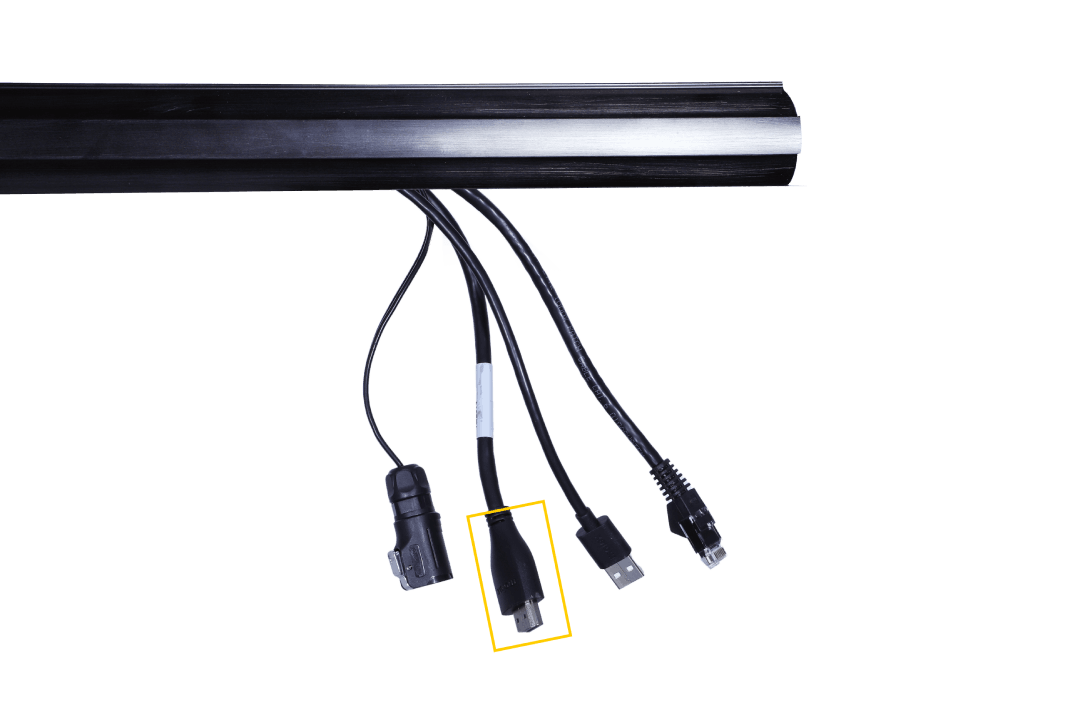
Fig. 34 – Fixing the HDMI Cable
Step 1: Insert the HDMI Cable on the marked port of the VHU.
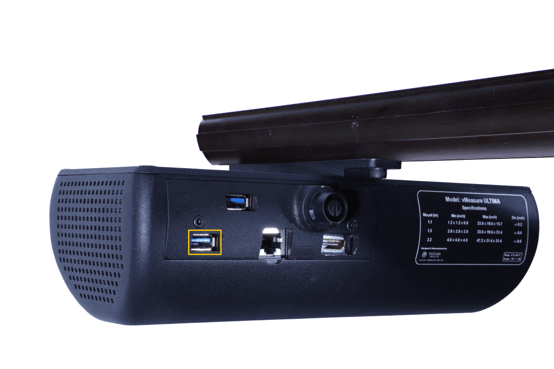
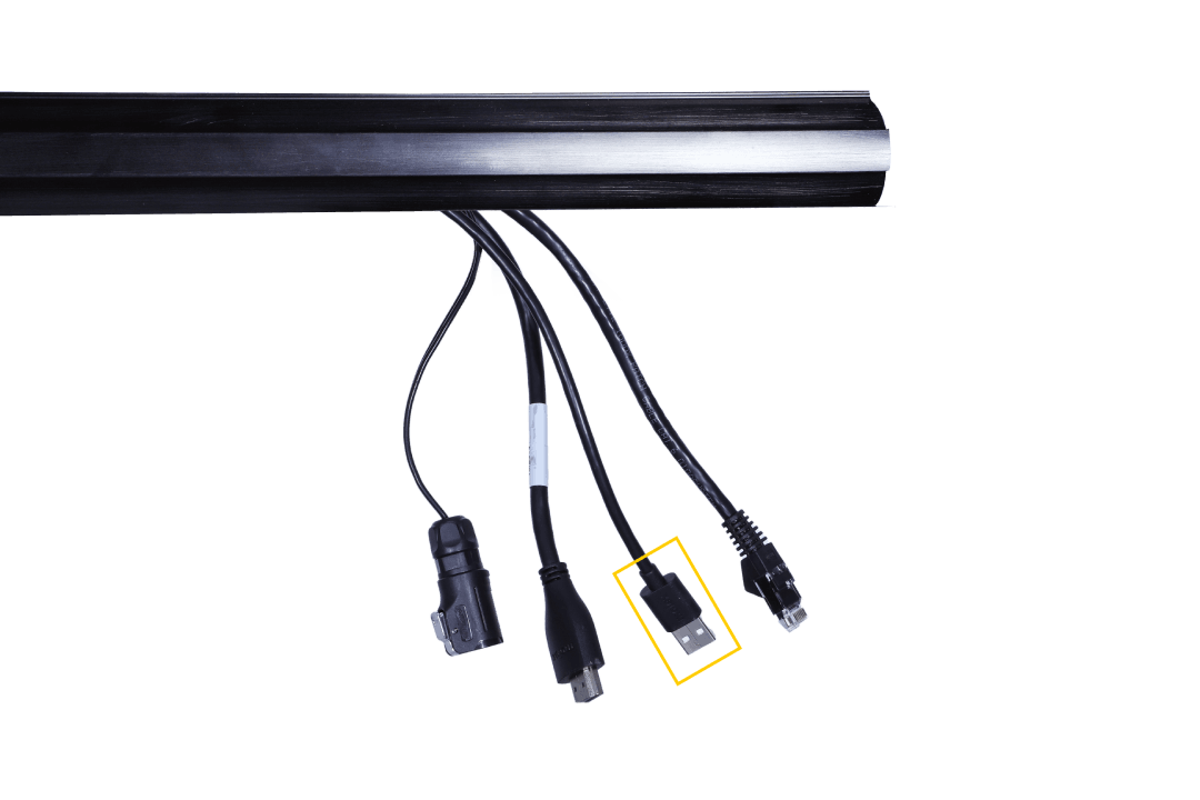
Fig. 35 – Fixing the USB Cable
Step 2: Connect the USB Cable on the marked port of the VHU.

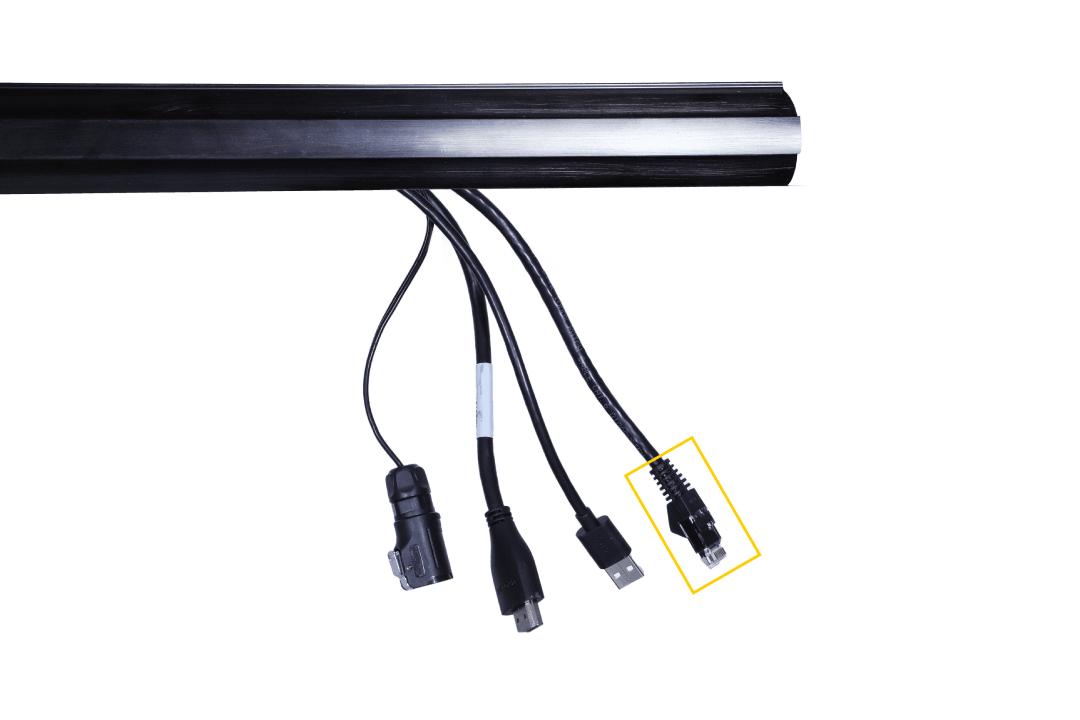
Fig. 36 – Fixing the Ethernet Cable
Step 3: Plug the Ethernet cable beside the power cable outlet.
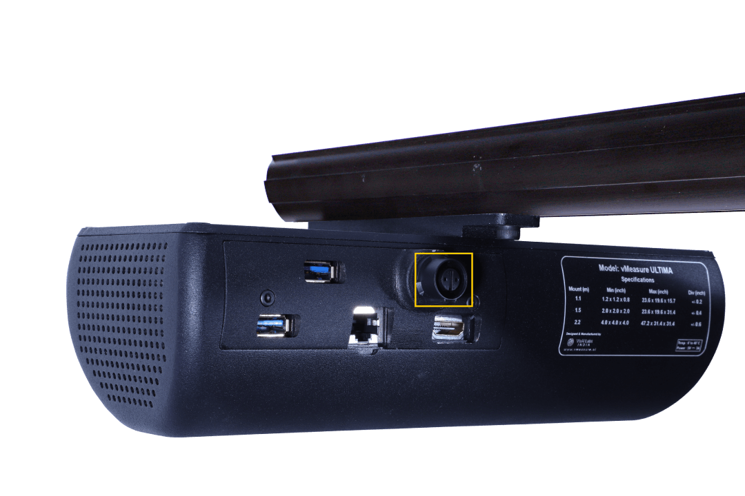
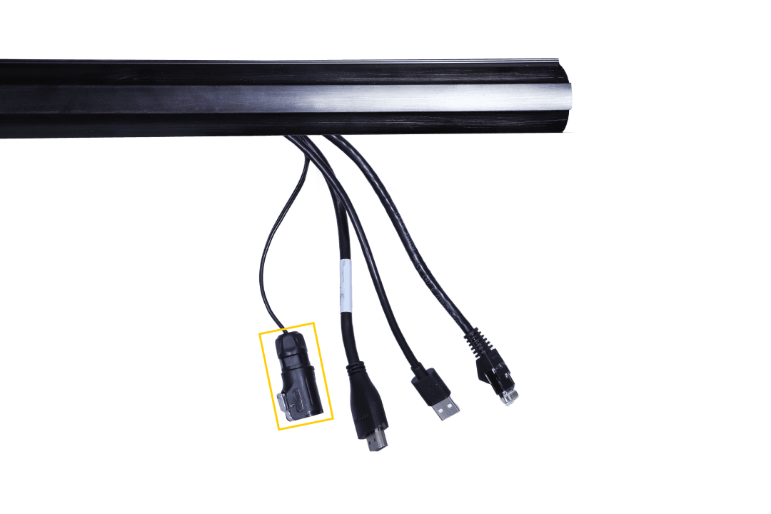
Fig. 37 – Fixing the Power Cable
Step 4: Plug the Power cable into the marked port.
Adjusting the pole to the desired configuration
Small SKU mode with weighing scale configuration
The All Parcel Mode with weighing scale configuration is the default dimensioning mode. That is, the pole height will be at 1.5 meters with a few additional meters to factor in the weighing scale’s height.
To switch to Small SKU mode with weighing scale configuration, find the mark ‘W 1.1’ on the horizontal pole and slide the vertical pole to it.
The ‘W’ refers to the vMeasure Ultima Parcel setup with a weighing scale configuration.
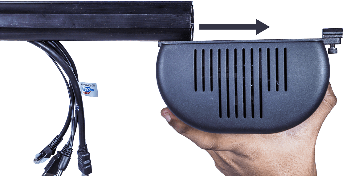
Fig. 38 – Full Setup of vMeasure Parcel Ultima
- Caution:
Remove the VHU before adjusting the pole height.
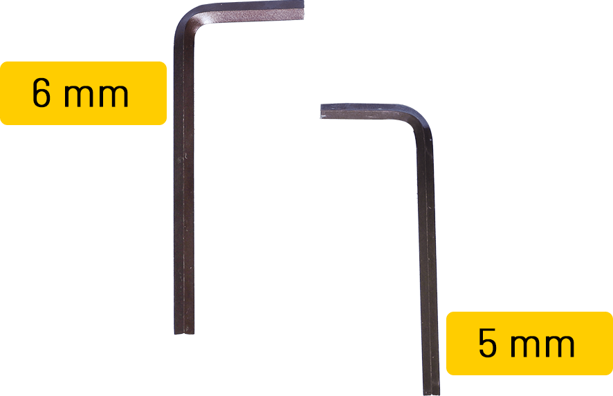
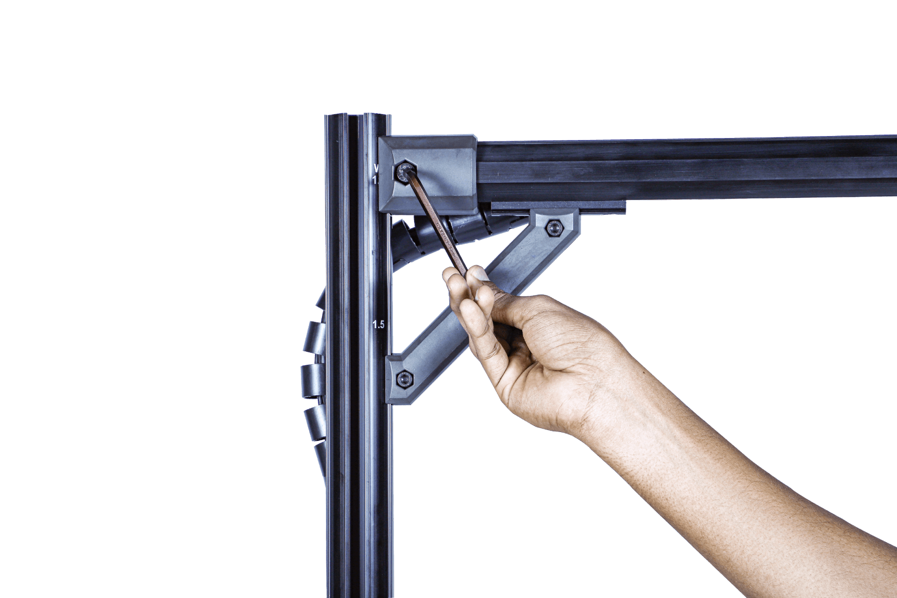
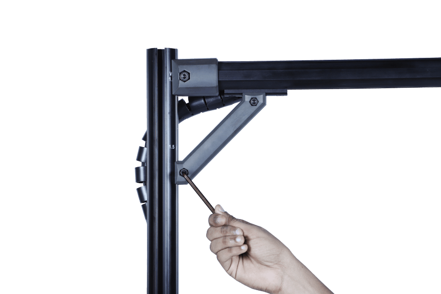
Fig. 39 – Removal of the Vision Head Unit
Step 1: Use the 6 mm Allen key to loosen the top screw and the 5 mm Allen key for the one below it.
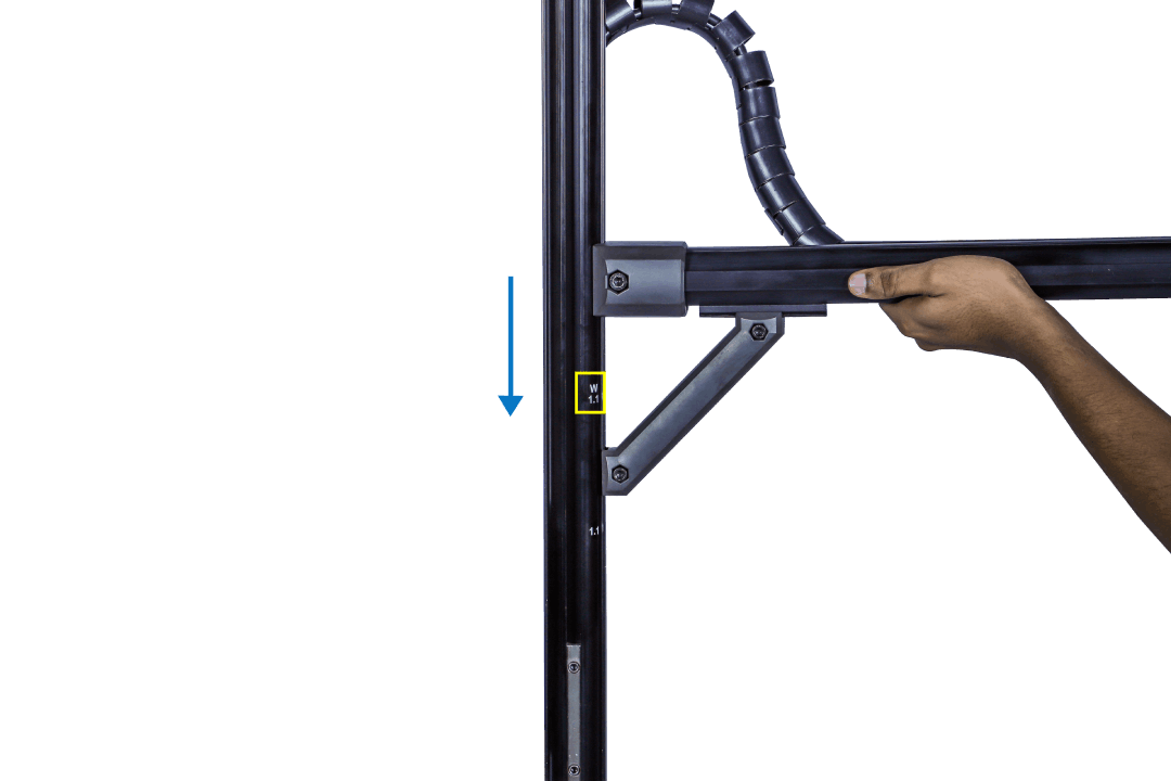
Fig. 40 – Height Adjustment to ‘W1.1’ (Small SKU Mode with Weighing Scale)
Step 2: Slide down the pole arm to ‘W1.1’ mark. Tighten both the screws using their respective Allen keys as given in Step 1.
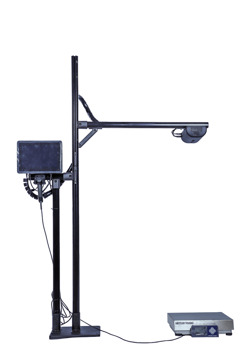
Fig. 41 – Full Setup of Small SKU Mode with Weighing Scale
You are all set to dimension on the Small SKU mode with weighing scale configuration.
All Parcel Mode with Weighing Scale
‘W 1.5’ is the appropriate height for All Parcel mode with weighing scale configuration. By default, the pole comes in this setting. So, there is no need to adjust the height for this dimensioning mode.
You are all set to dimension on the All Parcel mode with weighing scale configuration.
Small SKU mode without weighing scale configuration
Fig. 42 – Full Setup of Small SKU mode with Weighing Scale
Step 1: Use the 6 mm Allen key to loosen the top screw and the 5 mm Allen key for the one below it.
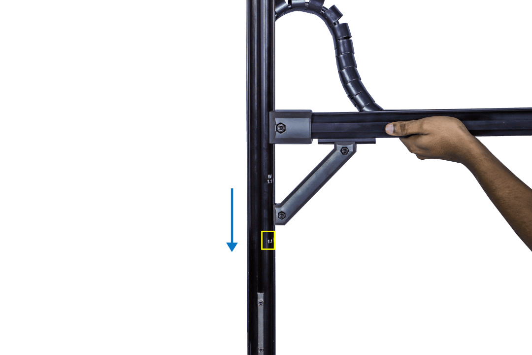
Fig. 43 – Height Adjustment to ‘1.1’ (Small SKU Mode without Weighing Scale)
Step 2: Slide down the pole arm to ‘1.1’ mark. Tighten both the screws using their respective Allen keys as given in Step 1.
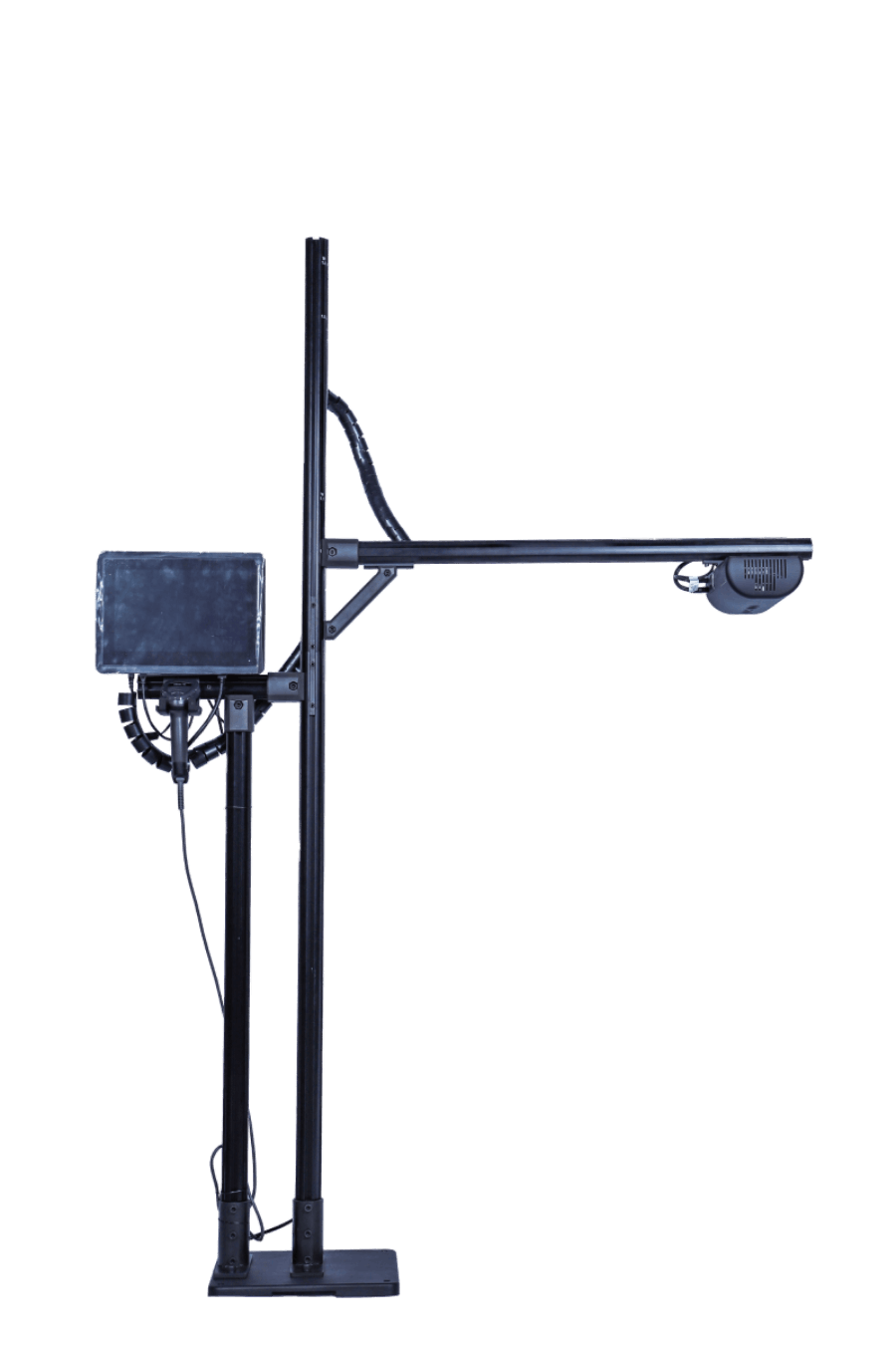
Fig. 44 – Full Setup of Small SKU Mode without Weighing Scale.
You are all set to dimension on the Small SKU mode without weighing scale configuration.
All parcel mode without weighing scale configuration
Step 1: Use the 6 mm Allen key to loosen the top screw and the 5 mm Allen key for the one below it.
Fig. 45 – Height Adjustment to Small SKU mode without Weighing Scale
Step 2: Slide down the pole arm to ‘1.5’ mark. Tighten both the screws using their respective Allen keys as given in Step 1.
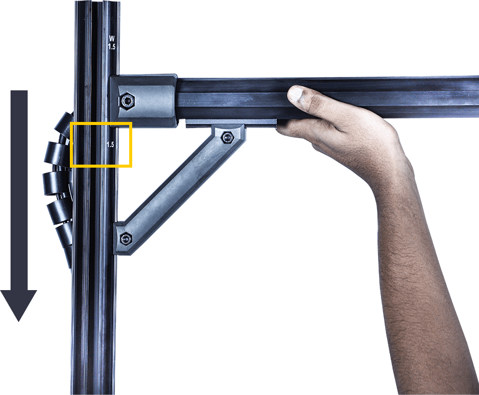
Fig. 46 – Height Adjustment to ‘1.5’ (All Parcel Mode without Weighing Scale)
You are all set to dimension on the All Parcel mode without weighing scale configuration.
vMeasure Parcel Ultima Application
Login
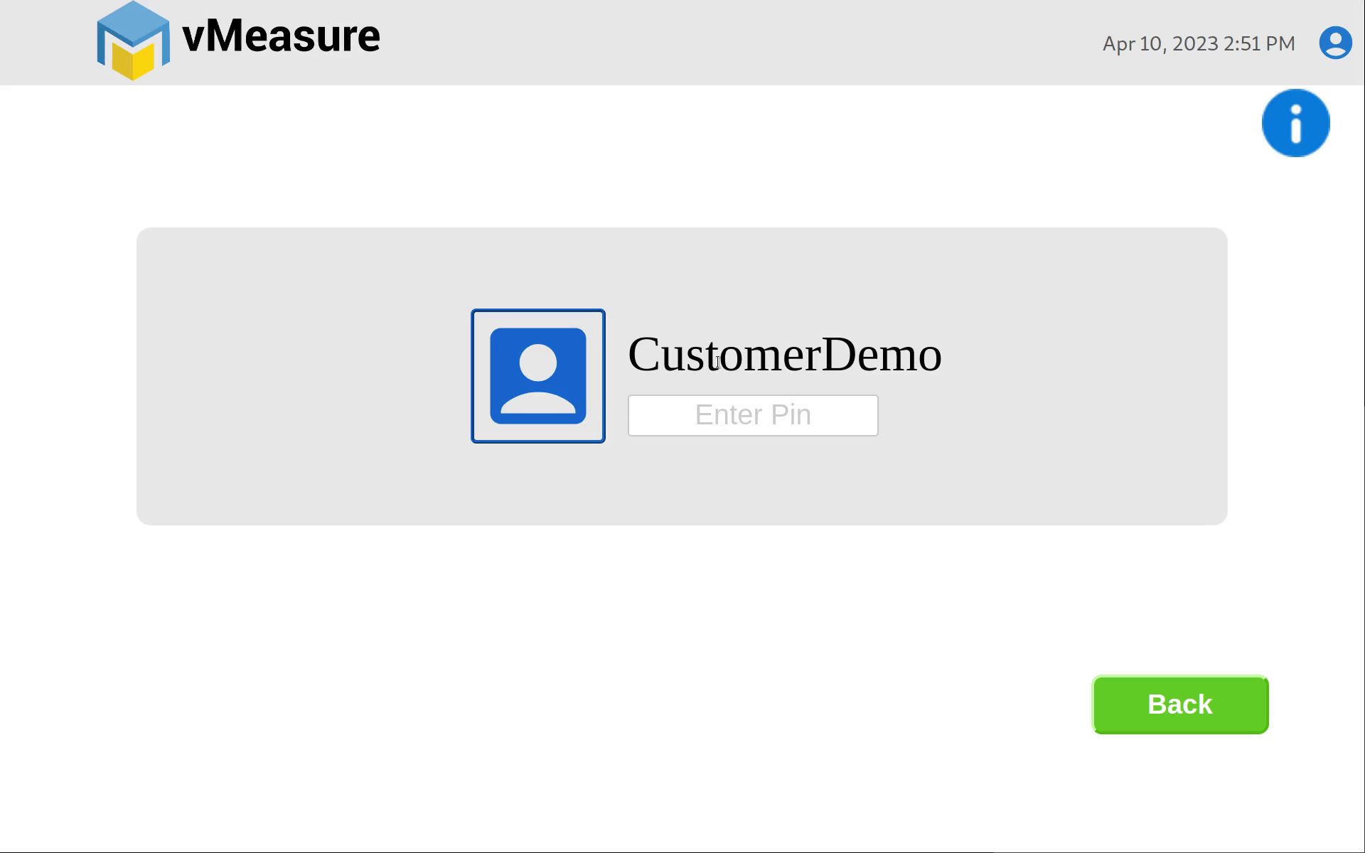
Fig. 50 – Login Screen
Step 1: Once the system boots, you will see the ‘Enter Pin’ screen. The pin will be sent by mail.
Fig. 51 – Input PIN
Step 2: You will now see the main menu.
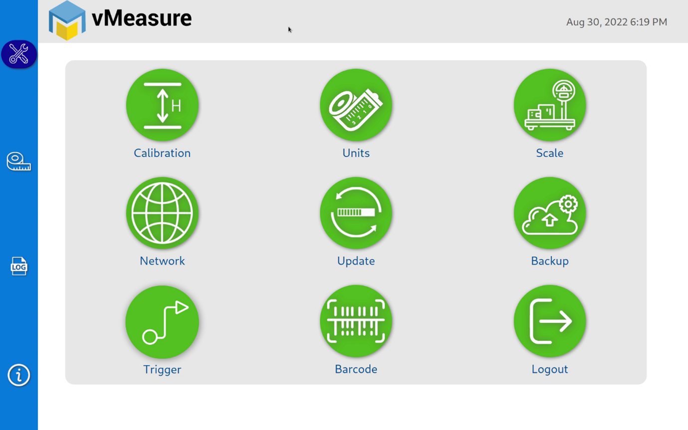
Fig. 52 – vMeasure Parcel Ultima Main Menu
Barcode and weighing scale integration
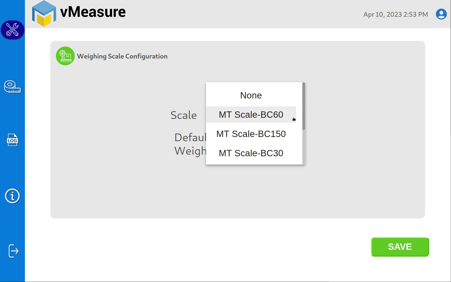
Fig. 53 – Scale Configuration Screen
Step 1: Select the integrated weighing scale from the dropdown menu

Fig. 54 – Barcode Configuration Screen
Step 2: Select the integrated barcode scanner from the dropdown menu Ensure that you configure the barcode before beginning calibration.
Calibration
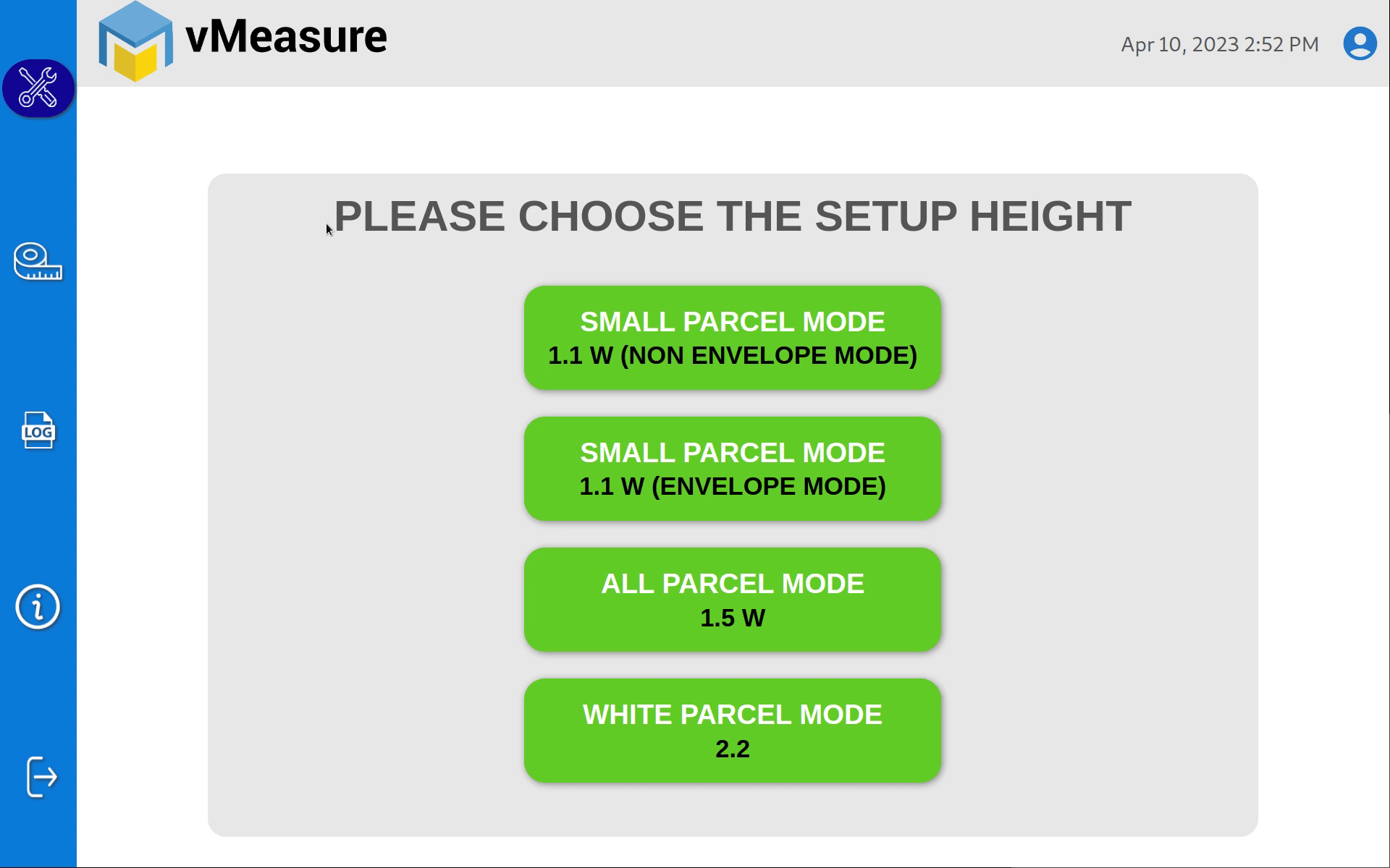
Fig. 55 – Calibration Screen
| Mode | Setup Height |
|---|---|
| Small SKU | 1.1 meters |
| All Parcel | 1.5 meters |
| White Goods Mode | 2.2 meters |
Step 1: Press the button to calibrate the device to the desired mode.
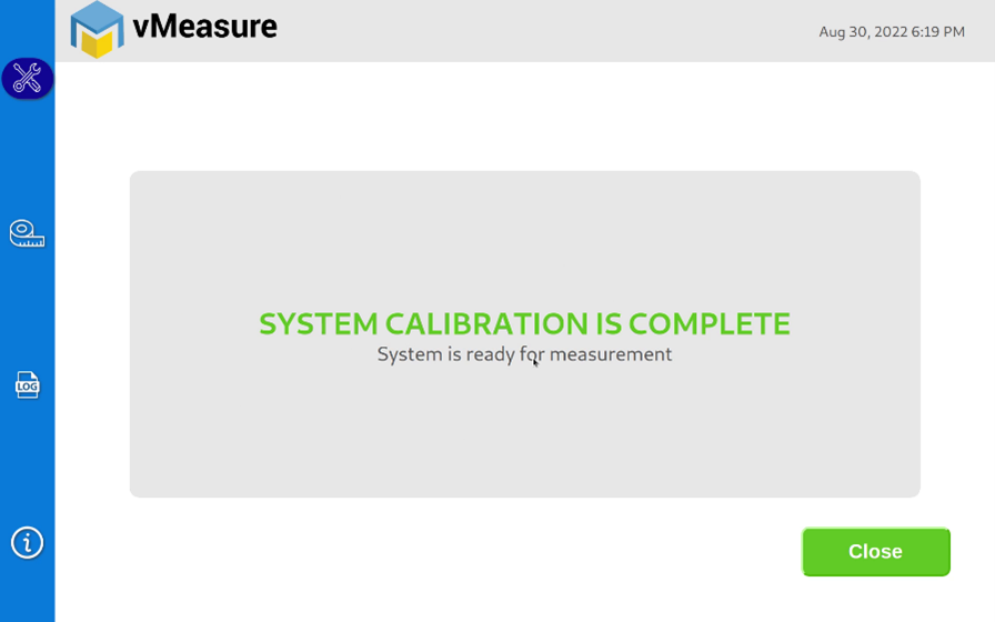
Fig. 56 – Successful Calibration
Wait for the system calibration to finish.
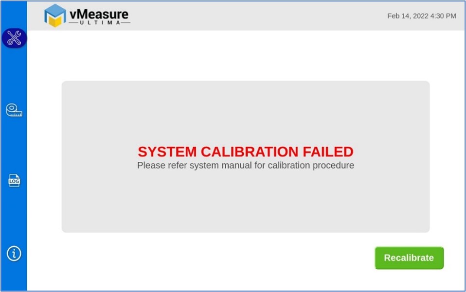
Fig. 57 – Calibration Error Screen
If the system fails to calibrate, press the ‘Recalibrate’
Refer to the ‘vMeasure Parcel Ultima Do’s and Don’ts’ document to make sure you haven’t left anything out. It will help you find what’s causing the calibration to fail.
If the problem persists, feel free to reach out our customer support team at vmeasure@visailabs.com
Go live!
Proceed with dimensioning SKUs after successful calibration.
There are multiple triggering options but in this Installation manual, the default triggering option is shown.
Step 1: Place the SKU under the camera. If you are using the vMeasure Parcel Ultima system with a weighing scale configuration, then place the SKU on the weighing scale.
Refer to the ‘vMeasure Parcel Ultima Do’s and Don’ts’ document for instructions regarding SKU placement under the camera.
Step 2: Scan the barcode and press the arrow button to continue
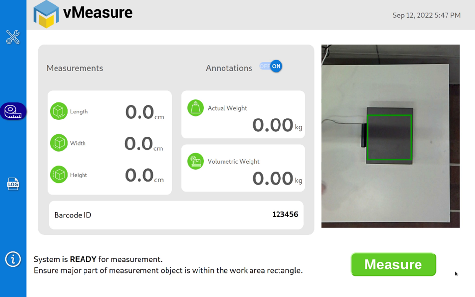
Fig. 58 – Measure Button
Step 3: Tap the ‘Measure’ button to dimension the SKU.

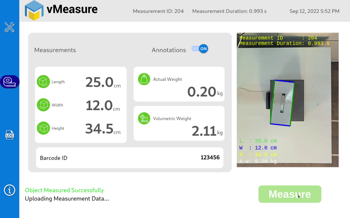
Fig. 59 – Measurement Successful
You have successfully dimensioned your SKU for the first time using vMeasure Parcel Ultima!
Installation Video
Walkthrough Video
Do’s and Don’ts
Support
If you have any questions about our product or applications, contact our support team – send an email, call us, or use our contact form.
It might take a few minutes so that we can support you as efficiently as possible. While contacting, tell us:
- The name of the product
- The serial number of the product
- The short description of the issue
- The peripherals connected to the system for answering your questions
We will be happy to help you!
Contact us,