


The Most advanced and easiest way to build website header and footer
Build sticky like content sticky, sidebar sticky, Menu sticky, footer sticky and more.
Discover the latest API feature updates, improvements and releases,
| Parameter | Valid Range | Brief Description |
|---|---|---|
|
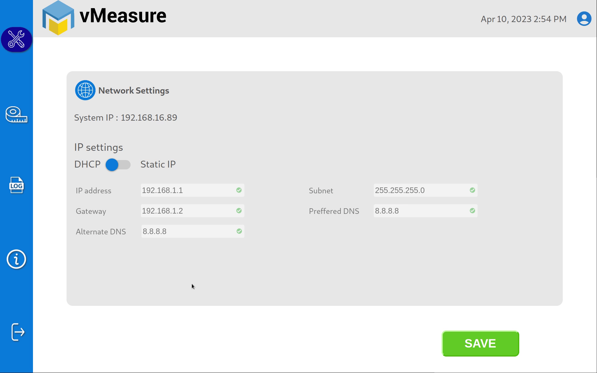
IP address |
xxx.xxx.xxx.xxx
Where x = 0 to 255 |
It is a unique address that identifies a device on the internet or a local network. You can only use static IPv4 addresses for permanent addresses.
For example: 192.168.6.40 |
|
Subnet |
xxx.xxx.xxx.xxx
Where x = 0 to 255 |
Subnet is a logical subdivision of an IP network.
For example: 255.255.255.0 |
|
Gateway |
xxx.xxx.xxx.xxx
Where x = 0 to 255 |
A gateway IP refers to a device on a network which sends local network traffic to other networks.
For example: 192.168.6.1 |
|
Preferred DNS |
xxx.xxx.xxx.xxx
Where x = 0 to 255 |
It is the primary choice to handle internet protocol mapping
For example: 8.8.8.8 |
|
Alternate DNS |
xxx.xxx.xxx.xxx
Where x = 0 to 255 |
It is used when the primary DNS server does not respond
For example: 8.8.4.4 |

| Cookie | Duration | Description |
|---|---|---|
| cookielawinfo-checkbox-analytics | 11 months | This cookie is set by GDPR Cookie Consent plugin. The cookie is used to store the user consent for the cookies in the category "Analytics". |
| cookielawinfo-checkbox-functional | 11 months | The cookie is set by GDPR cookie consent to record the user consent for the cookies in the category "Functional". |
| cookielawinfo-checkbox-necessary | 11 months | This cookie is set by GDPR Cookie Consent plugin. The cookies is used to store the user consent for the cookies in the category "Necessary". |
| cookielawinfo-checkbox-others | 11 months | This cookie is set by GDPR Cookie Consent plugin. The cookie is used to store the user consent for the cookies in the category "Other. |
| cookielawinfo-checkbox-performance | 11 months | This cookie is set by GDPR Cookie Consent plugin. The cookie is used to store the user consent for the cookies in the category "Performance". |
| viewed_cookie_policy | 11 months | The cookie is set by the GDPR Cookie Consent plugin and is used to store whether or not user has consented to the use of cookies. It does not store any personal data. |

Error: Contact form not found.